
Views: 0 Author: Site Editor Publish Time: 2026-07-30 Origin: Site


Bulk material handling systems face constant battles against material and air leakage. Fugitive dust, pressure loss, compliance fines, and product waste compound operational costs rapidly. Standard valves frequently fail under the stress of abrasive materials, high cycle rates, and pressure differentials. This continuous strain leads to premature seal degradation and severe system inefficiency. Shifting from reactive maintenance to proactive specification changes this trajectory. Evaluating engineered isolation gates based on seal design, actuation, and material compatibility remains critical for long-term reliability. We see this constantly in the field. Plant managers swap out cheap valves every three months instead of installing the right equipment once. You need to look at the mechanics of leakage and understand how pressure, abrasion, and deflection destroy standard seals. Stopping fugitive emissions starts with understanding the physical forces acting against your equipment.
Seal Integrity is Application-Dependent: Preventing leakage requires matching seal materials (elastomers, polymers, metal-to-metal) and geometries to the specific abrasive, chemical, and thermal properties of the bulk material.
Actuation Impacts Sealing Force: A high-performance pneumatic isolation gate provides the necessary, consistent seating force required to shear through standing material and maintain an airtight seal.
Deflection Causes Hidden Leaks: In high-tonnage applications, gate blade deflection under load creates microscopic gaps; specifying rigid, reinforced blade designs is non-negotiable.
Seal wear in bulk material handling stems from three primary mechanisms. Abrasive scouring occurs during every actuation cycle as hard particles drag across the sealing surface. When handling materials like silica sand, alumina, or clinker, this dragging action acts like sandpaper. Chemical degradation happens when incompatible materials interact with corrosive bulk solids, causing elastomers to swell, crack, or lose their elasticity. Thermal expansion introduces dimensional changes, warping metal components and breaking the seal contact. We often find that operators ignore the temperature spikes during pneumatic conveying, which bakes the seals until they become brittle.
Material packing presents another major failure point. Powders and granules often migrate into the valve pocket or bonnet during operation. Once material accumulates in these cavities, the blade cannot fully close. This incomplete stroke leaves a continuous bypass path for air and product. Improper installation exacerbates these issues. Misaligned flanges create uneven stress on the valve body. This distortion forces the gate blade to drag heavily on one side, accelerating wear patterns and destroying the seal geometry prematurely. You can usually spot this when one side of the blade shows deep scoring while the other looks untouched.
Inspect the blade surface for asymmetrical scoring marks indicating flange misalignment.
Check the valve pocket for compacted material that prevents the blade from seating fully.
Measure the ambient and internal operating temperatures to ensure they do not exceed the elastomer's rating.
Examine the seal profile for signs of chemical swelling or hardening.
Verify that the actuator stroke length matches the required travel distance for complete closure.
Maintaining a seal across a pressure boundary requires precise engineering. Gravity feed systems rely on material weight, but pneumatic conveying lines operate under positive or negative pressure. These pressure differentials actively seek escape routes. When a valve fails to close completely, the pressure forces fine powders through microscopic gaps. In dilute phase conveying, the air velocity can exceed 4,000 feet per minute. If a gap exists, the air will find it.
This high-velocity bypass creates a severe sandblasting effect. The abrasive particles erode the blade and seal materials rapidly, turning a minor leak into a catastrophic failure within days. Establishing baseline success criteria prevents these scenarios. A leak-proof system must demonstrate zero visible material leakage. It must prevent cross-contamination between batches. Finally, it requires measurable pressure retention over specified timeframes to confirm airtight integrity. We test this by isolating a pipe section and monitoring the pressure gauge. If it drops, you have a bypass issue.
Leakage Mechanism | Physical Indicator | Primary Cause | Field Solution |
|---|---|---|---|
Abrasive Scouring | Deep grooves on the blade surface | Hard particles dragging across the seal | Upgrade to hardened steel blades or polyurethane seals |
Material Packing | Blade stops short of full closure | Powder accumulating in the valve pocket | Install purge ports or use an open-body design |
Thermal Warping | Uneven gaps around the perimeter | Operating temperatures exceeding design limits | Specify high-temperature alloys and PTFE seals |
Pressure Bypass | Hissing sound or visible dust plumes | Inadequate seating force or worn elastomers | Increase actuation pressure or replace worn seals |
Selecting the right seal material dictates the lifespan of the valve. Polyurethane offers exceptional abrasion resistance, making it ideal for sand, gravel, and heavy minerals. Teflon (PTFE) provides superior chemical and heat resistance for aggressive pharmaceutical or chemical applications. Hardened steel seals handle extreme temperatures and highly abrasive clinker or ash where elastomers would melt or disintegrate. You have to match the shore hardness of the polymer to the particle size of your product. Fine powders require softer seals to fill the microscopic voids, while coarse aggregates need harder materials to resist tearing.
Active sealing mechanisms utilize system pressure or mechanical force to press the seal against the blade. Passive seals rely entirely on the initial compression set during assembly. Active displacement ensures longevity by compensating for gradual wear. Replaceable, mechanically retained seals outlast glued or molded alternatives. Mechanically fastened seals allow maintenance teams to perform field replacements quickly, reducing system downtime without removing the entire valve body from the line. We always recommend bolting the seals in place. Glued seals will eventually peel off when exposed to shear forces.
Actuation force determines whether a valve can close through a static column of dense material. Pneumatic cylinders deliver rapid, high-thrust actuation to shear through these obstructions. A High-Performance Pneumatic Isolation Gate utilizes oversized cylinders to guarantee consistent seating force. This force prevents the blade from stalling mid-stroke. If the cylinder is undersized, the blade will hit the material column and stop, leaving a massive gap for air and product to escape.
Adjustable cylinder cushions and precise air pressure regulation remain vital. Without cushions, the blade slams into the end stop. This impact damages seals, warps the blade, and fractures structural components. Integrating position sensors and limit switches provides verifiable closure confirmation for automated control systems. Fail-safe systems, including spring-return actuators or dedicated air-receiver tanks, ensure the gate closes automatically during sudden power or plant air losses. You need to know exactly where that blade is at all times. Relying on visual inspection is not an option in automated facilities.
Calculate the required shearing force based on the bulk density of the material.
Size the pneumatic cylinder to provide at least 20% more thrust than the calculated requirement.
Install flow control valves on the cylinder ports to regulate the opening and closing speeds.
Mount magnetic reed switches or inductive proximity sensors to verify the blade position.
Ensure the plant air supply provides consistent pressure, typically between 80 and 100 PSI.
Blade deflection occurs when heavy bulk material presses against the closed gate. The physics of this head load force the center of the blade downward. If the blade bows, it pulls away from the perimeter seals, creating immediate leak paths. High-tonnage applications require robust structural solutions to counteract this force. We see this constantly under large silos. A standard thin blade will bend like a piece of sheet metal under 50 tons of cement.
Thicker gate blades resist bending under immense pressure. Reinforced displacement pockets provide a rigid frame to support the blade during the final closing stage. Precision-machined guide rollers keep the blade perfectly centered throughout the stroke. Deflection resistance serves as a primary evaluation metric. Maintaining parallel seal engagement prevents structural fatigue and guarantees airtight performance under maximum load. You have to calculate the section modulus of the blade and ensure it can handle the static head pressure without exceeding the allowable deflection limits.
Standard slide gates excel in gravity flow applications but struggle in pressure-differential environments. Rotary airlocks handle pressure transitions well but suffer from continuous abrasive wear on the rotor tips. When standard slide gates face pressure, air escapes through the blade clearance gaps. The air will always take the path of least resistance, which is usually right past the packing gland.
Engineered modifications improve slide gate viability in low-pressure pneumatic systems. Bonneted designs enclose the blade entirely, preventing fugitive dust from escaping into the atmosphere. Purge ports inject clean compressed air into the valve body. This positive pressure barrier keeps abrasive material out of the seal cavity, extending the operational life of the gate. If you pump air into the bonnet at a higher pressure than the conveying line, the dust cannot migrate outward.
Valve Type | Pressure Handling | Abrasion Resistance | Best Use Case |
|---|---|---|---|
Standard Slide Gate | Poor (Gravity only) | Moderate | Silo discharge, hopper isolation |
Bonneted Slide Gate | Moderate (Low pressure) | High | Dust collection systems, dilute phase lines |
Rotary Airlock | Excellent | Low to Moderate | Continuous feeding into pressure lines |
Dome Valve | Excellent | Very High | Dense phase conveying, highly abrasive ash |
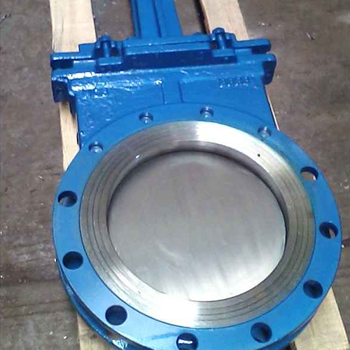
Liquid and slurry knife gates differ significantly from bulk material Isolation Gates. Standard knife gates push material into a closed chest cavity at the end of the stroke. In liquid applications, the fluid displaces. In bulk solid applications, the material packs tightly into the cavity. This packing causes the blade to jam, preventing full closure and causing severe leakage. We have pulled knife gates out of dry powder lines where the chest cavity was packed so hard it felt like concrete.
Modified knife gates address these limitations. Open-body designs allow displaced material to fall through the valve rather than packing into a cavity. Perimeter seals replace traditional packing glands, providing a tight seal against dry powders. These specific modifications make knife gates acceptable for certain dry bulk applications where standard designs would fail immediately. You have to specify a knife gate built specifically for dry solids, or you will spend all your time digging packed material out of the valve body.
Dome valves dominate highly abrasive, pressure-dense applications like fly ash and cement handling. The spherical dome rotates into place without dragging against the seal. Once closed, an inflatable seal expands against the dome. This mechanism eliminates abrasive wear during the actuation stroke entirely. The dome simply moves into position, and the seal does the rest of the work.
Inflatable seals inflate only after the valve achieves full closure. Before opening, the seal deflates, allowing the dome to move freely. The system demands a clean, dry, and highly reliable compressed air supply to operate the inflatable seals effectively. If your plant air is full of moisture or oil, the inflatable seals will degrade from the inside out. You must install dedicated air dryers and filters upstream of these valves.
Handling combustible dust requires strict adherence to safety regulations. Isolation gates play a critical role in deflagration and explosion isolation, aligning with NFPA 69 compliance standards. A compromised valve allows pressure waves and flame fronts to travel between connected vessels. If a dust explosion occurs in a dust collector, the isolation valve must close fast enough and seal tight enough to prevent the fireball from traveling back down the inlet duct.
Maintaining absolute seal integrity prevents the migration of fuel. If combustible dust leaks past a closed gate, it creates hazardous accumulations in surrounding areas. A fully sealed gate isolates the hazard, protecting connected equipment and personnel from catastrophic secondary explosions. You cannot cut corners on valves handling combustible dust. The structural integrity of the valve body must withstand the maximum reduced explosion pressure (Pred) of the system.
Upgrading to engineered valves in existing facilities introduces spatial constraints. High-performance gates often require larger footprints for heavy-duty cylinders and reinforced frames. Flange-matching issues arise when replacing older, proprietary valve designs with modern standard configurations. You will often find that the old valve had a non-standard bolt pattern, requiring you to drill and tap new holes in the field.
Mitigation requires careful planning. Custom transition pieces adapt new valves to existing pipework. Verifying stack-up height ensures the new assembly fits within the current vertical clearance. Structural support modifications may be necessary to handle the increased weight of heavier, deflection-resistant engineered valves. Do not hang a 500-pound valve on a thin-walled pipe without adding structural supports to the surrounding steelwork.
Measure the exact face-to-face dimension of the existing valve before ordering a replacement.
Verify the bolt hole pattern and flange outside diameter to ensure compatibility.
Check the vertical and horizontal clearance for the new pneumatic cylinder and limit switches.
Design custom spool pieces if the new valve is shorter than the existing gap.
Weld additional support brackets to the structural steel to carry the weight of the new assembly.
Proper commissioning dictates future reliability. Technicians must verify the air supply pressure meets the actuator's requirements. Calibrating limit switches ensures the control room receives accurate open and closed signals. Testing the valve under both dry-run and fully loaded conditions confirms the blade shears through the material without stalling. You have to run the valve with material in the line. A dry run tells you nothing about how the valve will perform under a head load.
Establishing a baseline preventative maintenance schedule prevents unexpected failures. Maintenance teams must prioritize regular seal inspections and actuator lubrication. Monitoring the system for early signs of bypass leakage, such as minor pressure drops or slight dust accumulation, allows for scheduled repairs before catastrophic failure occurs. Keep spare seal kits on the shelf. Waiting two weeks for a replacement seal while your line blows dust into the atmosphere is unacceptable.
Preventing leakage requires engineering the gate to the specific material and pressure characteristics of the system. Relying on standard valves for demanding bulk material applications guarantees failure. Prioritize inflatable seals for high-abrasion environments, rigid slide gates for heavy gravity loads, and robust pneumatic actuation for automated reliability. Stop treating valves as disposable commodities and start treating them as engineered solutions.
Audit all current material transfer points for visible dust or measurable pressure drops.
Document bulk density, particle size, and system temperature for your specific application.
Consult a specialized valve manufacturer to match seal geometry and actuation force to your material data.
Implement a strict preventative maintenance schedule focused on seal wear and actuator performance.
A: Leakage primarily results from abrasive seal wear, material packing in the valve pocket, and blade deflection under heavy loads. Improper air pressure can also cause the blade to stall mid-stroke, leaving a bypass gap for air and material.
A: Inflatable seals remain deflated while the valve blade or dome moves into the closed position. Once fully closed, compressed air inflates the seal, pressing it tightly against the closing member to create an airtight barrier without dragging wear.
A: In pressure-differential and hazardous material applications, the acceptable visible leakage rate is zero. The system must retain pressure and prevent any cross-contamination or fugitive dust emissions to meet operational and safety standards.
A: Replacement frequency depends entirely on the material abrasiveness and cycle rate. Highly abrasive applications may require quarterly replacements, while light-duty systems can run for years. Regular inspections dictate the actual schedule.
A: Standard slide gates are designed for gravity flow and typically fail in pressure environments. Engineered modifications, such as bonneted enclosures and clean air purge ports, are required to make slide gates viable in low-pressure pneumatic systems.
A: It features oversized pneumatic cylinders for high-thrust shearing force, rigid deflection-resistant blades, adjustable cushions to prevent slamming, and active sealing mechanisms designed specifically for abrasive or challenging bulk materials.

