
Views: 0 Author: Site Editor Publish Time: 2026-07-29 Origin: Site


Valve failure in high-temperature ash handling systems leads to severe operational and financial consequences. Unplanned outages halt power generation and incineration processes. Compromised seals create safety hazards and environmental compliance violations due to fugitive dust emissions. The core problem lies in the operating conditions. Standard industrial valves degrade rapidly when exposed to extreme thermal stress, which often exceeds 1,000°F (538°C). When you combine this heat with the highly abrasive nature of fly and bottom ash, conventional materials and standard seating mechanisms simply cannot survive.
Plant engineers must establish a rigorous technical framework for evaluating isolation gates. This evaluation focuses heavily on advanced material science, specialized body geometry, and robust actuation reliability. By prioritizing these engineering factors over basic off-the-shelf specifications, facilities ensure continuous, safe plant operation while mitigating the risks of catastrophic thermal binding and abrasive wear.
Thermal and Abrasive Synergy: Selecting the right gate requires balancing high-temperature alloy capabilities with abrasion-resistant designs to prevent thermal binding and premature wear.
Actuation Matters: A High-Performance Pneumatic Isolation Gate often provides the optimal balance of speed, reliability, and failsafe operation in automated ash handling environments.
Seal and Body Geometry Integrity: Metal-to-metal seating, lug-style body designs, and specialized high-temp packing are non-negotiable for preventing fugitive dust emissions and maintaining vacuum/pressure boundaries.
Auxiliary Thermal Protection: Protecting pneumatic lines, limit switches, and solenoids from extreme radiant heat using specialized high-temp insulation is critical to preventing actuator control failures.
Long-Term Value Over Initial Cost: Upfront capital expenditure must be weighed against maintenance frequency, ease of inline repair, and operational lifespan in severe service conditions.
Ash handling environments in power generation, biomass facilities, and municipal solid waste incineration present punishing conditions for mechanical equipment. A successful deployment means the valve cycles reliably without jamming, maintains a strict seal against hazardous dust, and withstands continuous abrasion over thousands of operational hours. Understanding specific failure modes is the first step in selecting the correct equipment.
Thermal expansion dictates valve performance in high-heat applications. When temperatures spike during boiler operations or ash transfer phases, the metal components of the gate body and the blade expand at different rates. This differential expansion alters the internal clearances designed into the valve at ambient temperatures. If engineering tolerances are too tight, the expanding blade wedges against the body or seat. This causes thermal binding. Jamming prevents the gate from opening or closing, effectively paralyzing the ash handling system.
When the system cools during a shutdown or a drop in load, the metal contracts. If the gate was closed while hot and expanded, subsequent cooling causes components to shrink away from each other. This results in a loss of seal integrity. Proper engineering accounts for thermal cycles by utilizing materials with predictable expansion coefficients. Dynamic seating arrangements maintain contact pressure regardless of temperature fluctuations.
Ash is not a uniform material. The characteristics of the ash dictate the specific wear mechanisms the equipment will face. Fly ash is fine, fluid-like, and highly penetrative. It acts almost like a liquid when aerated. This allows it to migrate into the smallest crevices of a valve body, packing glands, and seating areas. Because of its high silica content, fly ash is extremely abrasive. It scours metal surfaces as it flows past. Valves handling fly ash require tight tolerances and specialized packing to prevent material ingress.
Bottom ash presents a completely different challenge. It is heavy, dense, and often contains large, irregular clinkers. When bottom ash drops through a chute, it subjects the blade and body to severe impact forces. The abrasive nature of bottom ash causes deep gouging and rapid material loss on exposed surfaces. Equipment designed for bottom ash requires thicker body constructions, heavy-duty deflection cones, and hardened blade edges capable of crushing or shearing through solid obstructions without bending or fracturing.
Ash Type | Physical Characteristics | Primary Wear Mechanism | Required Valve Features |
|---|---|---|---|
Fly Ash | Fine, fluid-like, aerated, high silica | Scouring, penetration into crevices | Tight tolerances, specialized packing, purge ports |
Bottom Ash | Heavy, dense, large clinkers | Impact forces, deep gouging | Thick body, deflection cones, hardened shearing edges |
Containing hazardous ash dust is a strict regulatory and safety requirement. Fugitive emissions pose severe respiratory risks to plant personnel. They also trigger substantial environmental fines. Equipment must maintain an absolute seal against the outside environment. This is complicated by pressure dynamics within pneumatic conveying lines. Ash systems often operate under significant positive pressure or deep vacuum to transport the material.
Maintaining a tight seal against these pressure differentials requires robust packing systems and rigid body structures. If the blade deflects under pressure, it creates a leakage path. The equipment must provide bidirectional sealing capabilities. This ensures that whether the system is pushing or pulling the ash, hazardous dust remains entirely contained within the piping infrastructure.
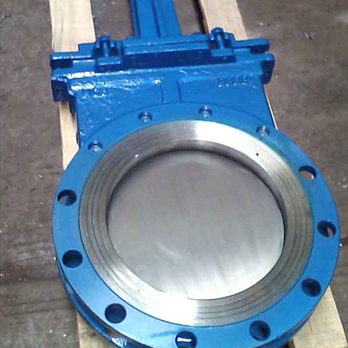
To survive severe conditions, equipment must be built with specific anatomical features. Standard water or slurry valves fail rapidly. The solution requires a purpose-built architecture focusing on body strength, advanced metallurgy, and specialized sealing technologies.
The structural integrity of the body determines its ability to withstand pipeline stresses and pressure loads. Wafer-style bodies are thin. They are designed to be sandwiched between two pipe flanges. While lighter and easier to install, they rely on the surrounding pipe for structural support. In high-temperature systems, thermal expansion of the piping exerts massive forces on a wafer valve. This potentially warps the body and destroys the seal.
Lugged body designs are vastly superior for severe service. A full lugged body features tapped holes that allow it to be bolted directly to the mating flanges. This robust construction provides significant structural rigidity. It resists pipeline bending moments and thermal stresses. A lugged design is critical for safety. It allows for dead-end isolation. Piping on one side can be removed for maintenance while the unit remains securely bolted to the pressurized side. This protects workers from hazardous ash flow.
Standard carbon steel and cast iron lose mechanical strength rapidly as temperatures exceed 800°F (426°C). In high-temperature applications, these materials warp, scale, and eventually fail catastrophically. Material selection focuses on specialized alloys capable of maintaining structural integrity and resisting oxidation at elevated temperatures.
310 Stainless Steel: Frequently utilized for temperatures up to 1,200°F (649°C). High chromium and nickel content provides excellent oxidation resistance.
Superalloys (Hastelloy, Inconel): Required for extreme environments. These materials retain yield strength under massive thermal loads.
Refractory Linings: Cast into the body in certain bottom ash applications where temperatures are extreme. They insulate structural metal from direct heat.
Elastomer seals, such as EPDM or Viton, are useless in high-temperature systems. They melt, burn, or become brittle and shatter within hours of exposure. Severe service requires metal-to-metal seating arrangements. The blade and the seat must be precision-machined to create a mechanical seal.
To combat extreme abrasion, metal seating surfaces are enhanced with hardened overlays. Stellite or Tungsten Carbide coatings are applied via plasma transfer arc welding to wear areas. This provides a surface hardness that resists the scouring action of the ash. For the atmospheric seal around the blade, high-temperature graphite or braided ceramic packing is utilized. These materials withstand heat while maintaining enough flexibility to compress against the moving blade and prevent fugitive dust emissions.
Ash packs into any available void within a body. If ash accumulates in the seating area or the chest, the blade cannot close fully. To prevent this, equipment for ash service incorporates active purge systems. Air or steam purge ports are drilled into the body. This allows high-pressure fluid to blast seat cavities clear of compacted ash just before the blade completes its closing stroke.
Mechanical self-cleaning features are equally important. The leading edge of the blade is often beveled to create a sharp knife edge. This design allows the blade to shear through standing columns of ash or crush brittle clinkers. It pushes displaced material out of the seating area rather than compacting it into the bottom of the body.
The mechanical body is only one part of the system. Actuation and control components are highly vulnerable to extreme radiant heat. Pneumatic tubing, solenoid valves, and electronic positioners melt or short-circuit if exposed to ambient temperatures surrounding a hot ash hopper.
Protecting auxiliary components requires specialized thermal barriers. High-temperature insulation materials must be installed between the heat source and control accessories. Actuators should be mounted on extended standoffs. This moves them out of the direct radiant heat zone, ensuring automated controls remain functional and reliable.
Selecting the right structural approach depends heavily on the specific application, the nature of the material, and spatial constraints. Different architectures offer distinct advantages and limitations in severe service environments.
Knife gate valves are heavily utilized due to their ability to cut through media. A heavy-duty lug knife gate features a blade that exits the body through a packing gland. This design is inherently self-cleaning. The blade pushes material out of the way as it closes. Knife gates are particularly effective in handling wet ash or highly compacted dry ash where shearing force is required.
Slide gate valves operate entirely within an enclosed body. The blade slides back and forth inside a sealed bonnet. The blade never exits to the atmosphere. This makes slide gates exceptionally good at preventing fugitive emissions in dry bulk solids handling. Because the blade retracts into an internal cavity, slide gates are more susceptible to material packing if not properly equipped with purge systems. The choice depends on the balance between shearing capability and absolute emission control.
It is important to contextualize where isolation equipment sits within the broader system. Rotary airlocks and double dump valves are continuous feeding mechanisms. They meter ash out of a hopper while maintaining a pressure boundary. They are constantly moving and subject to continuous wear.
Isolation equipment is typically installed directly above these feeding mechanisms. It is not used for metering. It is used strictly for on/off isolation. When the rotary valve requires maintenance due to wear, the isolation equipment is closed to hold back the column of hot ash. This allows maintenance personnel to safely remove downstream equipment without shutting down the entire boiler.
For standard applications with predictable temperatures and pressures, standardized severe-service equipment may be sufficient. These off-the-shelf solutions offer faster lead times and proven performance profiles. Legacy plant retrofits often present unique challenges that require custom engineering.
If a facility has non-standard flange dimensions, extreme spatial limitations, or unique metallurgical requirements, a custom-engineered solution is necessary. Custom solutions allow engineers to tailor face-to-face dimensions, modify actuator orientation, and select specific alloy combinations that match the exact operational footprint of aging infrastructure.
In automated environments, the method of actuation is critical. Pneumatically actuated solutions provide distinct advantages in terms of speed, reliability, and integration with plant control systems.
Ash conveying systems operate in batches. A hopper fills with ash, a valve opens to dump the material, and the valve closes so the line can be pressurized. This requires rapid open and close cycles. Electric actuators are often too slow for batch conveying. They take several minutes to stroke a large unit. Pneumatic cylinders stroke a unit in seconds. This keeps the batch process synchronized and efficient.
To integrate with the plant's Distributed Control System (DCS), pneumatic units are equipped with limit switches and smart positioners. These devices provide real-time feedback to the control room. They confirm the unit is fully open or fully closed. This feedback loop prevents the conveying system from activating before the unit is in the correct position.
Operating automated controls in hot, dusty environments requires strict adherence to electrical safety codes. Junction boxes, solenoids, and switches must meet specific creepage and clearance requirements. This prevents arcing in high-voltage or high-temperature conditions. Dust accumulation creates conductive paths, making adequate spacing between electrical terminals vital.
Compliance standards dictate the selection of these accessories. In areas where combustible dust is present, ATEX or NEMA 7/9 ratings are mandatory to prevent explosions. Safety Integrity Level (SIL) certifications may be required for control components. This ensures they meet reliability metrics demanded by modern plant safety protocols.
Power outages and losses of plant air pressure are realistic scenarios in heavy industrial facilities. When these events occur, the equipment must fail to a safe position. This is almost always the closed position to prevent uncontrolled ash dumping.
Pneumatic systems achieve this through spring-return cylinders or accumulator tanks. If air pressure is lost, a heavy-duty mechanical spring forces the unit closed. Alternatively, an accumulator tank stores enough compressed air to execute one final closing stroke. To maintain reliability, the plant air supply must be clean, dry, and regulated. Moisture or debris in air lines rapidly degrades cylinder seals and clogs solenoid valves.
When equipment sits closed under a heavy column of hot ash for an extended period, material compacts and sinters. This creates massive static friction against the blade. Standard actuator sizing calculations fail to open the unit under these conditions. They only account for pipeline pressure and basic friction.
Engineers specify oversized pneumatic cylinders designed to deliver exceptional breakaway torque. By increasing the bore size of the cylinder, the actuator generates the massive initial thrust required to crack the blade loose from compacted ash. This ensures reliable operation even after weeks of static operation.
Selecting the right equipment is only part of the equation. Practical realities of installing and maintaining the equipment dictate the true success of the deployment. Focusing on long-term operational stability ensures initial engineering effort translates into tangible plant reliability.
Replacing legacy equipment during a plant outage is a high-pressure evolution. Retrofitting modern severe-service units into older piping systems reveals flange mismatches or face-to-face dimension discrepancies. If the new unit is thicker than the old one, piping must be cut and re-welded. This significantly extends downtime.
High-temperature units built from heavy alloys are substantially heavier than standard units. Facilities evaluate existing structural supports and pipe hangers to ensure they bear the increased weight. Failure to properly support heavy equipment leads to pipeline sagging. This places immense stress on flanges and causes catastrophic failure.
Maintenance labor is a significant factor in plant operations. Equipment that requires complete removal from the pipeline for basic service is detrimental to efficiency. Severe service units should be designed for inline serviceability.
Features such as accessible packing glands allow maintenance technicians to tighten or replace the atmospheric seal while the unit remains bolted in place. Replaceable seat rings and bolt-on deflection cones enable rapid repair of primary wear components during short outages. The ability to rebuild the unit inline drastically reduces maintenance hours and minimizes the need for heavy rigging equipment.
Relying on proprietary, single-source components creates significant operational risk. If a custom internal part fails and the vendor has a long lead time, the plant faces an extended outage. Standardization mitigates this risk.
Facilities prioritize equipment that utilizes readily available, interchangeable wear parts. Establishing a strong relationship with a vendor who maintains a robust inventory of spare parts ensures critical components are dispatched immediately when required. This includes packing material, seat rings, and pneumatic rebuild kits.
Standard industrial valves are entirely inadequate for high-temperature ash handling. The combination of extreme thermal expansion, aggressive abrasion, and the need for absolute dust containment requires purpose-built equipment. Success in these severe environments depends on selecting robust lugged body designs, utilizing high-temperature alloys, and implementing metal-to-metal seating with active purge systems.
Plant engineers must carefully evaluate the actuation method. Oversized pneumatic systems with failsafe mechanisms provide necessary speed and power. By prioritizing long-term serviceability and robust construction, facilities eliminate safety hazards and unplanned outages associated with equipment failures.
Audit current failure rates to identify specific problem areas in ash handling lines.
Compile accurate process data, including maximum operating temperatures, pressure differentials, and ash bulk density.
Consult with a severe-service engineer to specify correct metallurgy and actuation for your operational footprint.
Implement a standardized maintenance schedule focused on inspecting packing glands and verifying pneumatic air quality.
A: Jamming, or thermal binding, occurs when the blade and body expand at different rates due to extreme heat. If engineering tolerances do not account for this thermal expansion, metal components wedge against each other, preventing operation.
A: Elastomer seals like EPDM or rubber melt, burn, or become brittle when exposed to extreme temperatures, which often exceed 1,000°F. Severe service requires precision-machined metal-to-metal seating to maintain a reliable seal.
A: A lugged body bolts directly to pipe flanges, providing superior structural rigidity to resist pipeline stresses. It allows for dead-end isolation, meaning downstream piping can be safely removed while pressure is held back.
A: Pneumatic actuators and controls are protected using thermal barriers such as fiberglass blankets, mica wraps, and ceramic shields. Mounting actuators on extended standoffs moves them away from the direct heat source.
A: Fly ash is extremely fine and fluid-like, allowing it to penetrate tiny crevices and packing glands. Its high silica content makes it highly abrasive, requiring very tight machining tolerances and specialized packing to prevent fugitive emissions.
A: High-performance pneumatic units use failsafe mechanisms, such as heavy-duty spring-return cylinders or accumulator tanks. Upon losing air pressure, these mechanisms automatically force the unit into a safe position, typically closed, to prevent uncontrolled ash flow.

