
Views: 0 Author: Site Editor Publish Time: 2026-07-31 Origin: Site


An incorrectly sized pneumatic actuator on an isolation gate compromises system safety, halts production, and accelerates equipment wear. When operators trigger a shutdown, the expectation is immediate, decisive action. If the actuator fails to deliver, the consequences ripple across the entire facility. The core problem lies in the tension between capital efficiency and operational reliability. Undersizing an actuator leads to stalling under peak differential pressure, leaving gates partially open during critical moments. Oversizing causes mechanical damage to the gate stem over time and wastes expensive compressed air with every cycle. Finding the exact balance requires more than a simple rule of thumb.
This guide provides a rigorous, evidence-based framework for calculating thrust requirements, applying appropriate safety factors, and specifying actuators. By understanding the mechanics of isolation gates, engineers can ensure reliable performance and extend the lifespan of their critical infrastructure.
Thrust Dictates Size: Actuator sizing must begin with the isolation gate’s peak thrust requirement, heavily influenced by differential pressure and media friction.
The Double Pressure Baseline: Always calculate pneumatic cylinder force based on the facility’s minimum available air supply pressure (to guarantee operation) and check against the maximum supply pressure (to prevent mechanical damage).
Mandatory Safety Margins: Industry standards dictate a 25% to 50% safety factor above the calculated peak torque/thrust, depending on media characteristics (e.g., clean fluids vs. abrasive slurries).
Fail-Safe Requirements: The choice between double-acting and spring-return (fail-safe) cylinders fundamentally alters the sizing math and physical footprint of the actuator.
Stroke and Speed Control: Accurate sizing must account for physical stroke length matching and control accessories (solenoids, quick exhausts) that impact air flow dynamics.
The primary function of isolation gates, including knife gate valves and slide gates, is strictly binary. They must be either fully open or fully closed. Unlike control valves that modulate flow, isolation gates require linear motion to drive a solid plate through a media stream. Success is defined by the actuator's ability to generate enough linear force to overcome all resistance and achieve a tight seal. You cannot rely on partial strokes. The system demands absolute isolation to protect downstream equipment and personnel.
Engineers must evaluate the breakout force required to initiate movement from a dead stop. This initial force is always higher than the running force needed to keep the gate moving. When a gate sits closed for extended periods, media can settle, harden, or crystallize around the seating area. The actuator must punch through this buildup without hesitation.
Differential pressure creates the most significant hurdle for actuator sizing. When an isolation gate is closed, the pressure difference across the blade pushes it hard against the downstream seat. This creates immense friction. The actuator must generate sufficient breakout force to drag the gate across this seat under maximum load conditions. If you calculate thrust based on zero pressure, the valve will stall the moment it faces real-world process conditions.
Consider a scenario where a 12-inch gate holds back 100 psi of water. The total force pushing the gate against the seat is massive. The friction coefficient between the gate material and the seat material determines how much of that force translates into resistance against the actuator. Metal-to-metal seats have different friction profiles than resilient elastomer seats.
The material flowing through the pipeline directly impacts the required force. Clean water presents minimal resistance. However, dry bulk solids, heavy slurries, or corrosive gases introduce variables like specific gravity, viscosity, and particulate buildup. Abrasive materials can pack into the valve body, significantly increasing the breakout force required to initiate movement.
Media Type | Friction Impact | Typical Safety Factor Required |
|---|---|---|
Clean Water / Air | Low - Minimal buildup or resistance | 25% |
Light Slurry / Wastewater | Medium - Moderate particulate settling | 30% - 40% |
Heavy Slurry / Mining Tailings | High - Severe packing and abrasion | 50%+ |
Dry Bulk Solids (Cement, Ash) | Very High - Compaction in valve body | 50% - 75% |
The physical distance the gate must travel to fully clear the flow path dictates the required cylinder stroke. This stroke length directly influences the lateral stability of the actuator and the volume of compressed air required per cycle. Mismatched stroke lengths can result in incomplete closure or unnecessary mechanical stress on the valve components. If the stroke is too short, the gate restricts flow and suffers premature wear. If the stroke is too long, the piston bottoms out violently, damaging the cylinder internals.
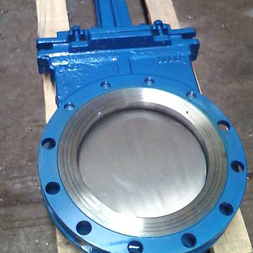
Before performing any calculations, engineers must compile a comprehensive dataset. Missing or assumed data leads to inaccurate sizing. Establish a standardized list of data points required for every installation. Do not guess these values. Pull the actual piping and instrumentation diagrams (P&ID) and consult the process engineers.
Valve type and size: Identify the exact port diameter and the specific design of the gate (e.g., through-conduit, push-through).
Maximum system operating pressure: Determine the highest pressure the system will see during normal operation.
Maximum differential pressure: Calculate the worst-case pressure drop across the closed gate.
Media details: Document abrasiveness, solids concentration, specific gravity, and operating temperature.
Air supply pressure: Record the minimum and maximum compressed air supply pressure at the exact valve location, not at the compressor.
Speed and cycle frequency: Define the required opening and closing speed, along with how often the valve cycles per day.
Fail-safe position: Specify if the valve must Fail Open, Fail Closed, or Fail Last upon loss of air or power.
Gathering this data upfront prevents costly rework later in the project. A common mistake is using the compressor's rated output pressure rather than the actual pressure available at the valve after line losses and concurrent pneumatic demands.
The foundation of accurate sizing is calculating the total required thrust. This involves summing three distinct forces: Seat Friction Force, Packing Friction Force, and the Stem Piston Effect. Seat friction is driven by differential pressure. Packing friction is the resistance from the seals around the stem. The stem piston effect accounts for the line pressure acting on the cross-sectional area of the stem itself. Always source accurate friction coefficients directly from the valve manufacturer.
The formula for total thrust looks like this: Total Thrust = (Area of Gate x DP x Seat Friction Coefficient) + Packing Friction + (Stem Area x Line Pressure). You must calculate this for both the opening stroke and the closing stroke, as the forces often differ. For example, opening a valve against high DP requires massive breakout force, while closing it might require less force but must overcome the media flow.
Once the required thrust is known, calculate the force the pneumatic cylinder can generate. The foundational formula is Force equals Supply Pressure multiplied by Piston Area. To find the piston area, use the formula involving the cylinder bore diameter. It is crucial to note the difference in available force between the extend stroke (which uses the full piston area) and the retract stroke (where the area of the stem reduces the effective piston area).
Cylinder Bore (Inches) | Extend Area (Sq. In.) | Retract Area (Sq. In.) *Assumes 1" Stem | Force at 80 PSI (Extend) |
|---|---|---|---|
4.00 | 12.56 | 11.78 | 1,004 lbs |
6.00 | 28.27 | 27.49 | 2,261 lbs |
8.00 | 50.26 | 49.48 | 4,020 lbs |
10.00 | 78.54 | 77.75 | 6,283 lbs |
Conduct a minimum pressure audit of the site's compressed air system. Determine the absolute minimum guaranteed pressure at the valve location, accounting for line losses and peak facility demand. Sizing must be based on this minimum pressure to guarantee operation. If the plant air drops to 60 PSI during shift changes, your actuator must still generate enough thrust at 60 PSI to move the gate.
Conversely, evaluate the Maximum Allowable Stem Load (MASL). Calculate the peak thrust generated at the maximum possible supply pressure to ensure it does not exceed the mechanical limits of the valve stem and gate. If the plant air spikes to 120 PSI, a massive cylinder might generate enough force to buckle the valve stem or punch the gate through the bottom of the housing. You must check both ends of the pressure spectrum.
Theoretical thrust calculations represent ideal conditions. They do not account for long-term wear, media buildup, transient pressure spikes, or minor fluctuations in air supply. Relying solely on raw math guarantees eventual failure in real-world industrial environments. A valve installed today will not have the same friction profile five years from now. Packing hardens, seats wear, and media leaves deposits.
Engineers must apply a safety factor to bridge the gap between theoretical math and operational reality. This factor ensures the actuator has reserve power to handle unexpected resistance without stalling.
Apply a 25% safety factor for clean, lubricating media like treated water or clean oils with stable operating temperatures. Increase this to a 50% or higher safety factor for severe service applications. This includes dry bulk solids, scaling liquids, paper stock, or highly viscous materials known to cause gate binding over time.
25% Margin: Standard for clean fluids, low cycle rates, and stable ambient temperatures.
30-40% Margin: Used for raw water, light slurries, and applications with moderate temperature swings.
50% Margin: Mandatory for heavy slurries, dry bulk powders, and highly corrosive environments.
75%+ Margin: Reserved for extreme applications like mining tailings or processes where media solidifies if flow stops.
Always cross-reference manual calculations with published manufacturer sizing charts. These charts often incorporate empirical data and specific valve characteristics that manual math might miss. Validating assumptions against manufacturer data ensures a robust and reliable actuator selection. If your manual calculation suggests a 6-inch cylinder, but the manufacturer chart recommends an 8-inch cylinder for the same DP, investigate the discrepancy. The manufacturer likely accounts for internal friction or seat geometries you overlooked.
Double-acting actuators use air to both open and close the gate. They typically have a smaller footprint and lower initial cost, but require sizing calculations for both stroke directions. You must ensure the retract stroke (which has less surface area due to the stem) still generates enough force to pull the gate out of the seated position.
Spring-return (fail-safe) actuators use air for one stroke and a mechanical spring for the opposite. The actuator must be sized large enough to overcome both the valve thrust and the significant compression force of the spring. When sizing a spring-return unit, you must calculate the spring end force (the weakest point of the spring stroke) to ensure it can still seat or unseat the valve under full differential pressure.
The speed of a High-Performance Pneumatic Isolation Gate depends heavily on control accessories. Solenoid valve flow coefficients and tubing diameters must match the actuator's volume to achieve target cycle times. If you put a small solenoid on a massive cylinder, the valve will crawl, regardless of the air pressure.
Quick exhaust valves (QEVs) are often necessary for rapid shutdown applications, allowing air to vent quickly and speeding up the stroke. Positioners can be added if partial stroking is required for testing, though isolation gates primarily operate fully open or closed. Ensure all accessories are rated for the ambient environment, especially in corrosive or high-temperature areas.
Evaluate cylinder barrel materials based on environmental corrosiveness. Options range from composite materials to aluminum and stainless steel. For true high-performance applications, specify cylinders with high-cycle seals and internal wear bands to withstand continuous operation in harsh conditions.
Aluminum Barrels: Standard for indoor, non-corrosive environments. Lightweight and cost-effective.
Composite Barrels: Excellent for corrosive environments like chemical plants or wastewater facilities. Immune to rust.
Stainless Steel: Mandatory for offshore, food-grade, or highly aggressive chemical applications.
Tie-Rod vs. Profile Design: Tie-rod cylinders offer easier maintenance and rebuild capabilities in the field.
Excessive force from an oversized actuator can bend valve stems, crush seats, or even punch the gate through the bottom of the valve body. Beyond mechanical stress, oversizing carries hidden economic impacts, including higher initial capital expenditure, larger mounting hardware requirements, and increased compressed air consumption during every cycle. Every cubic foot of compressed air costs money to generate. Oversized cylinders waste this energy continuously.
To mitigate this, always calculate the thrust at maximum plant air pressure and compare it to the valve's MASL. If the actuator can exceed the MASL, you must install pressure regulators to limit the force, or select a smaller cylinder and accept a lower safety factor.
Undersizing leads to operational failure. If the actuator lacks sufficient force, the gate stalls mid-stroke. This results in incomplete isolation, creating severe safety hazards during maintenance and leading to costly process contamination. A stalled gate in a slurry line will quickly pack with solids, requiring a complete system shutdown and manual cleanout.
Mitigate undersizing by strictly adhering to the minimum air pressure baseline and applying the correct safety factor based on the media. Never assume the plant air will always be at its rated maximum.
Extreme ambient temperatures affect O-ring elasticity, potentially causing leaks and loss of force. Standard nitrile seals harden in freezing temperatures and degrade in high heat. Specify Viton or low-temperature seals based on the installation environment.
Furthermore, the necessity of clean, dry instrument air cannot be overstated. Moisture and contaminants in the air supply lead to internal cylinder corrosion, premature seal failure, and erratic actuator performance. Install proper air preparation equipment, including filters and lubricators (if required by the cylinder manufacturer), immediately upstream of the control solenoid.
Audit your facility's compressed air system to determine the true minimum supply pressure at the valve location before starting any calculations.
Calculate the peak thrust requirement based on the maximum differential pressure and apply a safety factor of 25% to 50% depending on media abrasiveness.
Verify that the selected actuator's maximum force output at peak air pressure does not exceed the valve's Maximum Allowable Stem Load (MASL).
Select control accessories, such as solenoids and quick exhaust valves, that match the cylinder volume to ensure required cycle speeds are met.
A: Use the foundational formula Force equals Supply Pressure multiplied by Piston Area. Ensure you use the minimum guaranteed supply pressure at the valve location and calculate the area based on the cylinder bore diameter.
A: Industry standards dictate a 25% to 50% safety margin above the peak calculated thrust. Use 25% for clean fluids and 50% or more for abrasive, viscous, or dry bulk materials.
A: Sizing based on average or maximum pressure risks actuator stalling during facility-wide pressure drops. Using the minimum pressure ensures the gate operates reliably under worst-case conditions.
A: MASL is the maximum force a valve stem can withstand before bending or breaking. Actuators must be checked against maximum supply pressure to ensure they cannot exceed this structural limit.
A: Double-acting actuators only need to overcome valve friction and media pressure. Spring-return actuators must be upsized significantly to overcome those same forces plus the mechanical resistance of the fail-safe spring.
A: Yes. If the cylinder generates force exceeding the valve's Maximum Allowable Stem Load, it can bend the stem, damage the gate blade, or destroy the seating material.
A: The stroke length must precisely match the distance required to fully open or close the gate. Mismatched strokes cause incomplete isolation or apply unnecessary stress to the valve internals.

