
Views: 0 Author: Site Editor Publish Time: 2026-08-28 Origin: Site


Slag handling operates in a truly high-stakes environment. Extreme temperatures act constantly on all system components. Abrasive, variable loads amplify standard mechanical stresses every single day. You cannot treat these systems like standard bulk material handlers. Improper tensioning directly correlates to sudden, unplanned downtime. It creates severe safety hazards on the plant floor. It also accelerates equipment degradation at an alarming rate. Left unaddressed, these mechanical failures compound rapidly over time. Plant managers and reliability engineers need an evidence-based framework. You must evaluate your tensioning systems carefully. You also need reliable strategies to prevent belt tracking failures altogether. This article gives you the exact requirements for specifying a heavy-duty system. We will explore core mechanical principles. We will analyze various system configurations. Finally, we provide a concrete procurement checklist. You will learn how to maintain peak operational stability under the harshest conditions.
Optimal tensioning stabilizes the friction point between the drive pulley and the belt, directly preventing load-induced slippage and material spillage.
Dynamic load variations in slag handling require tensioning systems capable of real-time or active compensation to maintain baseline stability.
Upgrading to automatic or hydraulic tensioning systems yields a measurable reduction in premature belt wear and tracking-related faults compared to fixed mechanical take-ups.
Evaluating a High Performance Slag Conveyor requires looking beyond belt material to assess the integrated tension control strategy and load-response capabilities.
The physics of friction dictate bulk material movement. Baseline tension establishes the necessary grip. Engineers refer to this as tight-side tension (T1) and slack-side tension (T2). You need a specific ratio between them. This ratio allows the drive pulley to transmit torque efficiently. If tension falls too low, the pulley spins freely against the rubber. We call this drive slip. Drive slip burns the belt cover quickly. It also stops forward movement immediately. In a heavy-duty Slag Conveyor, maintaining the T1/T2 ratio prevents sudden load-induced stalls.
You must factor in the sheer weight of the material. Slag features an incredibly high bulk density. Steel or copper slag often exceeds 2,500 kilograms per cubic meter. When a sudden surge of this material hits the belt, it demands instant torque. The drive motor tries to deliver this torque. Without proper slack-side tension, the system fails to transfer energy. The mechanical grip simply breaks. Accurate tensioning keeps the belt firmly seated against the drive pulley lagging.
Heat introduces severe complications to tension control. Slag rarely cools uniformly. You frequently encounter localized hot spots during transit. These thermal variations impact the viscoelastic properties of the belt carcass. The rubber compound absorbs heat rapidly. It then undergoes micro-expansions. As the belt expands, overall system tension drops. Later, as the material exits, the belt cools. It contracts back to its original state. This dynamic cycle happens continuously.
Abrasive dust compounds this problem further. Silicate particles embed themselves into the pulley lagging. This alters the coefficient of friction dynamically. The system must adapt to both thermal expansion and surface abrasion simultaneously. Static tension settings cannot adjust to these minute, ongoing changes. The belt either goes slack or stretches too tight.
You must establish strict baseline success criteria. Operational stability requires consistent belt speed under maximum capacity. You cannot tolerate any drive slip during surge loads. Furthermore, you need uniform load distribution. The structure must not sag between the idler frames. Sagging creates a wavy profile. This profile agitates the slag aggressively. Agitation causes dust emissions and material spillage.
Achieving this stability demands continuous force application. The tensioning unit must absorb the shock of loading. It must also release slack during starting cycles. Once the system reaches its running speed, it must lock into an optimal steady state. You know you have achieved operational stability when tracking remains dead-center. The edges should never rub against the conveyor frame.
Insufficient tension causes immediate, visible problems. Material rollback acts as the primary indicator. When the belt sags between idlers, the material shifts backward. It spills over the edge of the idler trough. This spilled slag usually lands directly on the return rollers. It acts like grinding paste. The abrasive particles destroy roller bearings in days.
Drive-pulley lag presents another severe risk. The motor turns, but the belt hesitates. This hesitation creates friction heat. The heat vulcanizes the lagging prematurely. It makes the surface hard and slick. Once the lagging glazes over, it loses all grip. You then face a catastrophic failure loop. Less grip requires more tension. However, applying more tension to a glazed pulley often snaps the belt.
Many operators try to fix slippage by over-tightening the take-up. This creates hidden mechanical fatigue. Accelerated wear attacks every component. Bearings endure massive radial loads. Shafts bend microscopically under the strain. Over time, this bending causes metal fatigue. The tail shaft often snaps without warning.
The belt carcass also suffers immense damage. Localized stretching occurs near the splice joints. The steel cords or fabric plies pull apart slowly. Splice failure becomes inevitable. You will notice cupping along the belt edges. The belt refuses to lie flat. It rides up high on the wing idlers. This destroys the structural integrity of the rubber completely.
Uneven tension directly causes belt wandering. The belt always moves toward the side with less tension. If your take-up system applies asymmetric force, tracking becomes impossible. Many technicians adjust idlers to fight the wander. This treats the symptom, not the cause. Accurate, balanced tension acts as the primary prerequisite for tracking prevention.
Inspect the T2 (slack side) exiting the drive pulley for visible slack during startup.
Measure the temperature of the drive pulley lagging after one hour of loaded operation.
Check the splice joints for elongation, separation, or exposed internal cords.
Monitor the return run for excessive material spillage near the tail section.
Listen for high-pitched squealing from the tail pulley bearings under full load.
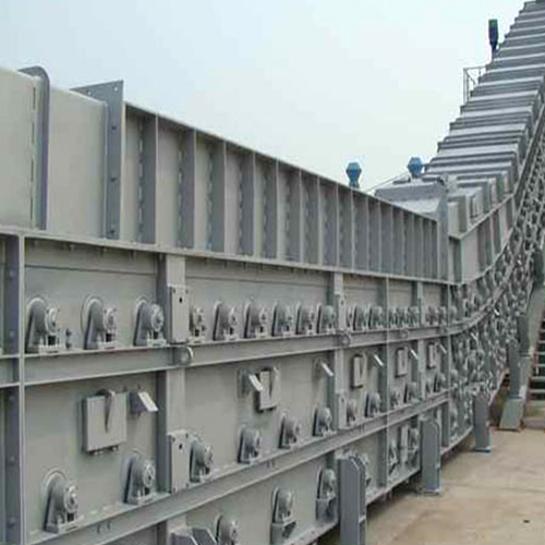
Specifying a High Performance Slag Conveyor requires looking beyond just the belt rubber. The integrated tension control strategy matters most. Different mechanical approaches yield wildly different uptime metrics. You must evaluate these options based on dynamic response capabilities.
Fixed mechanical take-ups rely on threaded rods. Maintenance crews turn large nuts to pull the tail pulley backward. This locks the pulley in place. They offer a very low initial cost. They feature simple, understandable maintenance procedures. Operators rarely need specialized training to use them.
However, they cannot adapt to dynamic loads. They lock the tension into a static state. Thermal expansion causes the belt to loosen. The screw take-up cannot pull the slack automatically. They also present a high risk of human error. Technicians often adjust one side more than the other. This induces severe tracking faults. We recommend these only for very short, light-duty runs. They are rarely ideal for heavy slag applications.
Gravity take-ups utilize a heavy mass block. This block hangs from cables or sits in a vertical tower. It applies constant, passive tension adjustment based purely on gravity. As the belt stretches, the weight drops. It pulls the slack out of the system. They remain highly reliable because gravity never fails.
Despite their reliability, they have strict limitations. They require significant vertical space. Many crowded plant floors cannot accommodate the tower structure. Furthermore, gravity systems react slowly. They struggle to handle sudden, violent load spikes. The mass block possesses inertia. When a heavy slag surge hits, the block bounces. This bouncing sends tension shockwaves through the belt carcass.
Automated systems represent the industry standard for minimizing Mean Time Between Failures (MTBF). These units utilize hydraulic cylinders or motorized winches. They monitor tension using load cells. When they detect a drop in tension, they react instantly. They push or pull the tail pulley to restore the exact setpoint.
You must evaluate them based on dynamic response times. Look for advanced PID (Proportional-Integral-Derivative) control models. These algorithms predict tension loss before it causes slippage. The automated logic prevents the system from over-correcting. Continuous, data-driven tension adjustment eliminates premature belt wear. It keeps the system running smoothly despite harsh environmental variables.
Comparison of Tensioning Systems for Slag Environments
System Type | Dynamic Response | Maintenance Complexity | Ideal Application |
|---|---|---|---|
Screw Take-Up | None (Static) | Low (Manual adjustment) | Short, light-duty material transfers. |
Gravity Take-Up | Slow (Inertia-bound) | Medium (Cable inspections) | Long runs with ample vertical space. |
Hydraulic/Auto | Instant (Active PID) | High (Fluid & sensor checks) | High-capacity, volatile slag handling. |
Accurate tension calculation requires rigorous engineering data. You cannot guess the required force. First, determine the belt modulus. This dictates how much the rubber will stretch under load. Next, calculate the peak load tonnage. You must use the absolute maximum surge weight, not the average hourly rate.
Incline angles drastically alter tension needs. Steep inclines require much higher T1 values to fight gravity. Operating temperatures also play a crucial role. High heat softens the belt. It requires lower baseline tension to prevent tearing. You must feed all these variables into standard CEMA (Conveyor Equipment Manufacturers Association) formulas. This establishes your absolute minimum and maximum tension boundaries.
Retrofitting advanced tensioning units requires careful structural planning. Hydraulic skids possess a large physical footprint. You must find secure deck space near the tail pulley. The structural rigidity of the existing frame matters immensely. Automated systems exert massive force quickly. If the steel frame is weak, it will buckle.
Sensor placements also require precision. Load cells must sit exactly parallel to the belt travel. Any angular misalignment corrupts the data. You may need to weld custom mounting brackets. Ensure the structural modifications do not impede routine maintenance access. The area around the tail pulley remains a high-traffic zone.
Automated systems introduce new points of failure. Sensor fouling presents the biggest risk. Slag environments generate extreme dust. Optical sensors fail almost immediately. You must use robust alternatives. We strongly recommend magnetic or ultrasonic sensors. Ensure all electronics carry IP65 or IP67 enclosure ratings. This protects them from dust ingress and water spray.
Hydraulic lines face risks from stray hot material. Route all hoses through armored steel conduit. Implement system redundancy wherever possible. If the primary pressure sensor fails, a backup must take over. This redundancy prevents the hydraulic unit from applying maximum force blindly. Proper safeguards ensure the automation protects the equipment rather than destroying it.
Enclose all hydraulic power units in climate-controlled, dust-proof cabinets.
Perform a full structural stress analysis on the tail section before installing hydraulic cylinders.
Train maintenance staff on reading PID controller fault codes.
Calibrate load cells quarterly using certified dead weights.
You must verify the vendor's engineering assumptions. Many suppliers quote systems based on static resting weight. This approach guarantees failure in slag applications. Demand calculations based on maximum dynamic load. Ask how the system handles a cold startup under a full surge load. The proposed tensioning unit must have enough reserve capacity to stretch the belt during extreme events. If the cylinder stroke is too short, the system will bottom out.
Evaluate the physical layout of the proposed system. Maintenance crews must access take-up bearings safely. They should not need specialized scaffolding. Hydraulic lines must feature quick-disconnect fittings. Counterweight tracks need clear access for debris removal. If a tensioning system requires extended shutdowns for simple greasing, it will fail. Crews simply skip hard-to-reach maintenance tasks. Prioritize designs that place control valves and grease banks on the outer walkway.
Never accept theoretical performance promises. Require vendors to provide empirical data. They must show modeling on how their configuration handles tracking. Ask for case studies involving comparable high-abrasion applications. You need evidence that their tensioning strategy stabilizes the friction point in real life.
Ask specific questions about their control logic. How does the PLC react if the belt slips? Does it trigger an alarm, or does it adjust the pressure automatically? A qualified vendor will gladly share these operational sequences. They will prove their system prevents slippage without accelerating mechanical fatigue.
Tensioning remains a dynamic operational necessity, not a set-and-forget parameter. Extreme thermal variables and dense loads constantly attack the friction point. If you rely on static adjustments, you guarantee accelerated wear. Proper tension dictates the lifespan of the entire mechanical chain. It protects bearings, splices, and the belt carcass itself.
Decision-makers must take proactive next steps. First, audit your current failure rates. Track how many hours your team spends fighting belt wander. Calculate the frequency of splice repairs. Next, consult with specialized engineering partners. Evaluate the feasibility of upgrading to active, automated tensioning systems. Stabilizing your system tension is the most effective way to eliminate unplanned downtime.
A: Environmental factors and dynamic load cycles dictate the exact frequency. You should perform baseline visual inspections weekly. Look for material sag or drive slip. We recommend recalibrating the tension during every scheduled preventive maintenance window. You must also adjust it immediately whenever tracking drifts occur. Do not wait for the belt to rub the frame.
A: You will notice premature bearing noise near the tail and drive pulleys. Look for excessive heat radiating from the pulley shafts. The edges of the belt will often begin cupping upward. You will also experience frequent splice degradation. The rubber at the joint will show visible stretching or tearing.
A: Yes, for high-capacity, critical-path operations. The prevention of catastrophic downtime easily justifies the premium of hydraulic or automated controls. They eliminate premature belt replacements. However, for highly constrained, short-distance, low-load transfer points, they remain unnecessary. Manual systems suffice for those minor applications.

