
Views: 0 Author: Site Editor Publish Time: 2026-07-30 Origin: Site


In industrial processing, material handling, and dust collection, power outages or pneumatic air supply failures are inevitable. The immediate mechanical response to these failures dictates whether a facility experiences a safe shutdown or a catastrophic event. Specifying the incorrect default state for isolation gates during a system failure can result in uncontrolled hazardous material release, severe equipment damage such as dead-heading blowers, or non-compliance with safety regulations like NFPA and OSHA. Determining whether an isolation gate should be fail-open or fail-closed requires a rigorous evaluation of process flow, material characteristics, and worst-case scenario hazard analysis. You must evaluate what happens when all utility inputs vanish simultaneously. The mechanical design must force the equipment into its safest configuration without human intervention. This guide provides an engineering-focused framework to make the correct specification for your facility.
Hazard Mitigation Dictates State: Fail-closed configurations prioritize containment and isolation of hazardous materials, dust, or fire, while fail-open configurations prioritize pressure relief, ventilation, and preventing upstream equipment damage.
Actuation Mechanics Matter: Achieving a true fail-safe state requires specific actuator designs, typically utilizing mechanical spring-return mechanisms, pneumatic trip valves, or dedicated air accumulators.
System-Wide Impact: The decision cannot be made in a vacuum; engineers must evaluate the cascading effects of a gate's failure state on upstream compressors, positive displacement blowers, and downstream processing equipment.
Compliance is Non-Negotiable: Regulatory standards for combustible dust (NFPA 69, NFPA 652), toxic gas, and process safety management (OSHA PSM) strictly govern the required failure state of critical isolation points.
Fail-safe does not mean failure-proof. It defines the predetermined, unpowered mechanical position a gate assumes upon loss of control signal, electrical power, or compressed air. Engineers design these systems to default to a position minimizing hazard. The chosen state depends entirely on the specific process risks. Industrial systems utilize three primary failure modes. Fail-Closed (FC) means the gate fully closes upon utility loss. This blocks material flow and isolates process zones. Fail-Open (FO) means the gate fully opens when utilities fail. This vents pressure and allows unobstructed flow. Fail-in-Place or Fail-Last (FL) means the gate maintains its current position. Engineers must analyze drift risk over time for FL configurations. Pneumatic leaks or mechanical vibrations can cause an FL gate to slowly shift, altering process conditions dangerously.
Mechanical spring-return pneumatic actuators represent the gold standard for reliable energy storage. These single-acting designs use compressed air to compress a heavy-duty spring. When air pressure drops, the spring forces the valve to its fail-safe position. They require no external power during an emergency. Double-acting cylinders paired with fail-safe air accumulators offer an alternative. These systems use pneumatic trip valves to direct stored air from a local reservoir into the cylinder during a failure. This approach works well for massive gates requiring force beyond standard spring capabilities. Electric fail-safe actuators utilize battery backup systems or mechanical spring-returns. High-torque applications often struggle with electric spring-returns due to size constraints. Battery systems require rigorous maintenance to ensure reliability during power outages.
Control accessories execute rapid state transitions. Solenoid valves configured to de-energize-to-trip ensure the system reacts instantly to electrical failure. Quick Exhaust Valves (QEVs) dump cylinder air directly to the atmosphere. This bypasses restrictive supply lines and dramatically increases actuation speed. You must size these components correctly based on the cylinder volume and required stroke time. Undersized QEVs will choke the exhaust air, slowing the gate's response time and potentially allowing a hazard to bypass the isolation point.
Failure Mode | Mechanism | Primary Use Case | Key Vulnerability |
|---|---|---|---|
Fail-Closed (FC) | Spring extends to push blade closed | Combustible dust isolation, toxic containment | Material jamming in the seat preventing full closure |
Fail-Open (FO) | Spring retracts to pull blade open | Pressure relief, blower protection | Uncontrolled release of process media downstream |
Fail-in-Place (FL) | Air trapped on both sides of piston | Continuous processes sensitive to sudden changes | Pneumatic drift over time due to seal leaks |
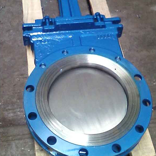
Fail-closed configurations dominate combustible dust isolation applications. They prevent deflagration propagation across processing zones, ensuring NFPA 69 compliance. Hazardous material containment also relies on fail-closed designs. They seal off toxic chemicals, corrosive gases, and highly abrasive materials from the environment. Fire and smoke suppression systems utilize fail-closed gates to isolate HVAC and process ductwork. This starves the fire of oxygen and prevents smoke spread. Gravity-fed bulk solids handling requires fail-closed mechanisms to prevent massive material spills. A power loss during silo discharge could flood downstream equipment if the gate remains open.
A fail-closed state ensures absolute compartmentalization of the facility during emergencies. It stops the movement of dangerous media instantly. This protects sensitive downstream equipment from sudden material surges when operators restore power. Containing the hazard at the source simplifies emergency response and cleanup procedures. Closing a gate against active flow introduces severe engineering challenges. Upstream overpressurization poses a significant risk. Trapping high pressure upstream can cause pipe, duct, or vessel rupture. Engineers must install secondary pressure relief systems to mitigate this danger.
Material compaction and jamming frequently plague fail-closed systems. Attempting to close a knife gate through a dense, static column of bulk solids often leads to incomplete closure. The blade may wedge against the material, leaving a dangerous gap. Specifying actuators with sufficient shear force is critical. The mechanism must cut through moving material columns during a sudden closure without bending the blade or stalling. You must calculate the required cutting force based on the bulk density of the material, the friction coefficient of the blade, and the cross-sectional area of the opening. Undersized actuators will fail to isolate the hazard.
Calculate the maximum expected material column weight above the gate.
Determine the shear strength of the bulk solid under compression.
Select an actuator that provides at least a 1.5x safety factor over the calculated required closing force.
Implement a self-clearing seat design to push displaced material out of the blade path.
Fail-open configurations excel in emergency pressure relief and venting. They instantly route overpressure to the atmosphere or safe containment vessels. Blower and compressor protection heavily relies on fail-open designs. They prevent positive displacement blowers from dead-heading. Pumping against a closed system leads to immediate mechanical failure or motor burnout. Emergency exhaust and cooling ventilation systems require fail-open gates. They ensure high-temperature systems or toxic fumes naturally draft out of occupied work areas during a power loss. Bypass line activation also uses fail-open logic. Diverting process streams to alternative safe routes prevents upstream process backups.
Failing open prevents catastrophic overpressure events and duct collapse. It provides an immediate, unpowered escape route for expanding gases. This allows for the safe, passive purging of lines during an emergency shutdown. Equipment remains protected from mechanical stress caused by blocked flow. The primary risk involves the uncontrolled release of process materials, dust, or hazardous gases. Operators must ensure secondary containment systems can handle the sudden influx. Failing open also causes the loss of process vacuum or nitrogen purge pressure. This requires extensive and costly restart and line-purging procedures once utilities return.
When designing a fail-open system, you must trace the discharge path. Venting a combustible dust cloud into an enclosed, unclassified area creates a secondary explosion hazard. The discharge must route to a safe location, typically outdoors, through structurally reinforced ductwork. You must also consider the environmental impact of the released material. Regulatory agencies may require reporting of unpermitted emissions resulting from a fail-open event. Balancing equipment protection against environmental compliance requires careful system design and potentially the inclusion of secondary filtration or scrubbing systems on the emergency vent line.
Deflagration isolation and emergency shutdown scenarios require millisecond response times. A standard gate cannot close fast enough to stop a flame front. A High-Performance Pneumatic Isolation Gate utilizes optimized porting, QEVs, and low-friction seals to achieve these critical speeds. Engineering calculations must verify the closure time against the expected hazard propagation speed. Seal integrity determines containment success. Engineers evaluate Teflon, metal-to-metal, elastomer, and inflatable seals. The chosen material must maintain a positive seal without active pneumatic pressure. Self-cleaning seat designs prevent material accumulation from obstructing complete closure. Abrasive dust easily packs into standard seat pockets, rendering the fail-safe mechanism useless.
Gate blades and bodies must withstand harsh environments during a static failure state. Abrasive media, high temperatures, and corrosive gases degrade standard materials quickly. Hardened alloys, specialized coatings, and robust structural designs ensure the gate remains intact and functional during an extended emergency shutdown. Explosion isolation barriers must comply with ATEX Directives and NFPA 69. These standards dictate structural strength and actuation speed requirements. Integrating isolation gates into Safety Instrumented Systems (SIS) requires specific Safety Integrity Level (SIL) ratings. SIL 2 or SIL 3 ratings demand rigorous failure mode analysis and redundant control architectures.
You must also evaluate the physical footprint of the high-performance actuator. Spring-return cylinders are significantly longer and heavier than standard double-acting cylinders due to the internal spring housing. Structural supports must accommodate this additional overhung load to prevent pipe stress and flange misalignment. In tight installations, you may need to specify a custom linkage or a different valve style to fit the required fail-safe mechanism into the available space.
Identify Most Severe Consequence of Power/Air Loss | |
|---|---|
Loss of Containment / Fire | Overpressure / Blower Damage |
Select: FAIL-CLOSED | Select: FAIL-OPEN |
Verify Actuator Shear Force & Material Compaction Limits | Verify Safe Discharge Routing & Emission Compliance |
Conduct a hazard analysis to identify the absolute worst-case scenario. Determine if the primary danger is overpressurization or loss of containment. Overpressurization leans toward a fail-open configuration. Fire propagation or toxic release demands a fail-closed setup. Trace the entire process flow. Document exactly what happens to upstream pressure, downstream supply, and intermediate storage when the gates change state. A localized safe state might trigger a catastrophic failure elsewhere in the facility.
Evaluate the system's behavior during a simultaneous electrical power loss and compressed air failure. The mechanical fail-safe mechanism must operate flawlessly without either utility. Relying on backup generators or secondary air compressors introduces unacceptable risk points.
Assess how the process media behaves during an unpowered transition. Abrasive dust, high-temp gas, dense slurry, and wet solids react differently. Determine if the material will bridge, pack, or seize the gate blade. The actuator must possess enough mechanical force to overcome these obstacles.
Map how the local actuator's fail-safe behavior aligns with the plant's centralized Distributed Control System (DCS) or Emergency Shutdown (ESD) logic. The local mechanical default must match the programmed software expectations to prevent conflicting commands upon restart.
Implementing Partial Stroke Testing (PST) verifies fail-safe spring or accumulator performance without disrupting active production. PST moves the valve slightly to confirm the mechanism is not stuck. Engineers must address the degradation of mechanical springs due to fatigue or internal corrosion. Regular inspection and replacement schedules prevent silent failures. High-performance Filter-Regulator-Lubricator (FRL) units prevent actuator stick-slip and valve sticking. Clean, dry air is non-negotiable for reliable operation. Desiccant air dryers avoid moisture freezing in cold climates. Frozen moisture easily locks the fail-safe mechanism, rendering the system defenseless during an emergency.
Designing control systems with time-delay relays or redundant solenoids prevents costly shutdowns from momentary electrical voltage dips. A fraction-of-a-second power loss should not trigger a massive facility shutdown unless absolutely necessary. Proper control architecture filters out these nuisance signals while maintaining true emergency responsiveness. You must also establish clear lockout/tagout (LOTO) procedures for fail-safe equipment. A spring-return actuator stores massive amounts of mechanical energy. Maintenance personnel must know how to safely release or mechanically block this energy before performing work on the gate or surrounding piping.
You must document all fail-safe settings and testing procedures in the facility's Process Safety Information (PSI) package. Operators need clear visual indicators on the plant floor showing the current state of the gate and its designated fail-safe position. Color-coded tags or highly visible mechanical position indicators help personnel quickly assess the system status during an emergency walkdown. Training programs must cover the expected behavior of these gates during a blackout, ensuring operators do not attempt to manually override a gate that has correctly moved to its safe position.
Establish a baseline for actuator performance during commissioning. Record the exact time it takes for the gate to reach its fail-safe position under normal process conditions. Compare future PST and full-stroke test results against this baseline. An increasing stroke time indicates internal friction, spring fatigue, or pneumatic exhaust restrictions. Address these issues immediately before the gate fails to operate during a real emergency.
Verify that the plant air supply system has sufficient capacity to handle the sudden demand of multiple gates resetting simultaneously after a power restoration. If dozens of large pneumatic actuators attempt to compress their heavy-duty springs at the exact same moment, the resulting pressure drop can starve the entire pneumatic network. Stagger the restart sequence in the DCS or install local air receivers to buffer the demand.
Inspect the mechanical linkages and clevis pins connecting the actuator to the gate blade. These components endure severe shock loads during a rapid fail-safe actuation. Look for signs of elongation, cracking, or excessive wear. A sheared pin disconnects the actuator from the blade, rendering the fail-safe mechanism completely useless regardless of how well the pneumatic system functions.
Ensure that limit switches and position sensors accurately reflect the true physical position of the gate blade, not just the position of the actuator shaft. If the connection between the actuator and the blade fails, the control system might read a "closed" signal while the gate remains wide open. Direct blade sensing provides the most reliable feedback for critical safety interlocks.
Review the environmental conditions surrounding the installation. Extreme ambient temperatures degrade pneumatic seals and alter the viscosity of lubricants. Specify high-temperature or low-temperature seal kits based on the actual operating environment. Protect the actuator and control accessories from direct exposure to corrosive chemicals, heavy washdown sprays, or excessive vibration from nearby equipment.
Maintain a critical spares inventory for all fail-safe components. Solenoid valves, QEVs, seal kits, and replacement springs should be readily available on-site. Waiting weeks for a replacement part forces the facility to either operate without the required safety barrier or shut down production entirely. Partner with manufacturers who offer rapid support and readily available replacement parts.
Conduct regular audits of the fail-safe logic in the DCS. Software updates or logic modifications can inadvertently alter the behavior of safety interlocks. Verify that the programmed response to a utility failure still aligns with the mechanical reality of the installed hardware. The software and hardware must work in perfect synchronization to ensure a safe shutdown.
Train maintenance personnel on the specific hazards associated with pneumatic trip valves and air accumulators. These systems store high-pressure air locally and can actuate the gate even when the main plant air supply is disconnected. Proper depressurization procedures are mandatory before beginning any maintenance work on double-acting fail-safe setups.
Evaluate the impact of process media buildup on the gate's moving parts. Sticky or hardening materials can glue the blade in place, preventing the spring from forcing it closed. Implement automated purge cycles or specify specialized non-stick coatings for the blade and seat to minimize material adhesion. Regular cleaning schedules are essential for maintaining reliable operation in difficult applications.
Consider the acoustic impact of rapid fail-safe actuation. QEVs dumping high-pressure air directly to the atmosphere generate significant noise. Install pneumatic silencers on the exhaust ports to protect personnel from hearing damage, but ensure the silencers do not restrict the exhaust flow and slow down the gate's response time. Size the silencers appropriately for the required exhaust volume.
Review the structural integrity of the ductwork or piping supporting the isolation gate. The sudden deceleration of a heavy gate blade closing at high speed transfers massive kinetic energy into the surrounding structure. Ensure the piping supports and flanges can withstand these shock loads without cracking or deforming. Reinforce the installation area if necessary.
Integrate the fail-safe gate status into the facility's alarm management system. Operators need immediate notification if a gate moves to its fail-safe position unexpectedly. The alarm should clearly indicate the specific gate, its location, and the suspected cause of the actuation. This allows for rapid troubleshooting and minimizes production downtime.
Establish a clear chain of command for authorizing the reset of a fail-safe gate after an emergency actuation. Operators must verify that the hazard has been cleared and the process is safe to resume before returning the gate to its normal operating position. Bypassing safety protocols to quickly restart production often leads to secondary accidents.
Document all maintenance and testing activities in a centralized computerized maintenance management system (CMMS). Track the failure history of each gate to identify recurring issues or premature component wear. Use this data to optimize maintenance schedules and justify equipment upgrades or replacements when necessary.
Consult with the gate manufacturer during the design phase to ensure the selected actuator and accessories are perfectly matched to the process requirements. Provide detailed information about the process media, operating pressures, temperatures, and required response times. The manufacturer's engineering team can help you avoid common pitfalls and select the most reliable fail-safe solution.
Perform a final functional test of the entire fail-safe system before putting the process into production. Simulate a complete loss of electrical power and compressed air simultaneously. Verify that every gate moves to its correct fail-safe position within the required timeframe. Do not rely on theoretical calculations alone; prove the system works in the real world.
Continuously monitor industry best practices and regulatory updates related to process safety and isolation gates. Standards evolve as new technologies emerge and lessons are learned from industrial accidents. Stay informed to ensure your facility remains compliant and utilizes the most effective safety measures available.
Foster a strong safety culture within the facility. Ensure all personnel understand the critical role of fail-safe isolation gates in protecting their lives and the environment. Encourage operators to report any unusual gate behavior or suspected maintenance issues immediately. A proactive approach to safety prevents minor problems from escalating into major disasters.
Regularly review and update the Process Hazard Analysis (PHA) for the facility. Process changes, equipment modifications, or new material introductions can alter the risk profile and necessitate a re-evaluation of the fail-safe strategy. Ensure the isolation gates continue to provide adequate protection against the current hazards.
Invest in high-quality, reliable equipment from reputable manufacturers. Cutting costs on critical safety components often leads to higher long-term expenses due to increased maintenance, production downtime, and potential accidents. Prioritize performance, durability, and proven reliability when selecting fail-safe isolation gates.
Maintain open communication with local emergency response agencies. Provide them with detailed information about the facility's hazards, safety systems, and fail-safe protocols. This ensures they are prepared to respond effectively in the event of an emergency and understand how the isolation gates will behave during a crisis.
Conduct post-incident investigations for any unexpected fail-safe actuations. Determine the root cause of the utility failure or control system error that triggered the event. Implement corrective actions to prevent a recurrence and improve the overall reliability of the process and safety systems.
Ensure all engineering drawings, piping and instrumentation diagrams (P&IDs), and control logic diagrams accurately reflect the installed fail-safe hardware and software. Keep these documents up-to-date and readily accessible to maintenance and engineering personnel. Accurate documentation is essential for effective troubleshooting and system modifications.
Provide ongoing training for engineering and maintenance staff on the latest fail-safe technologies and testing methodologies. Encourage them to attend industry conferences, participate in webinars, and read technical publications to expand their knowledge and skills. A well-trained workforce is the best defense against equipment failures and process accidents.
Establish a formal management of change (MOC) process for any modifications to the fail-safe isolation gates or their associated control systems. Require a thorough review by process safety engineers before implementing any changes to ensure they do not compromise the integrity of the safety barrier.
Regularly audit the facility's compliance with relevant safety regulations and industry standards. Identify any gaps or areas for improvement and develop a plan to address them. Proactive compliance management minimizes the risk of fines, penalties, and legal liabilities associated with safety violations.
Promote a culture of continuous improvement in process safety. Encourage employees to identify and implement innovative solutions to enhance the reliability and effectiveness of the fail-safe isolation gates. Recognize and reward individuals who contribute to a safer working environment.
Collaborate with other facilities within the organization or industry to share best practices and lessons learned related to fail-safe isolation gates. Participate in industry forums, working groups, and benchmarking studies to benchmark your facility's performance against peers and identify opportunities for improvement.
Leverage advanced diagnostic technologies to monitor the health and performance of the fail-safe isolation gates. Implement predictive maintenance programs based on data analytics and machine learning algorithms to identify potential failures before they occur. This proactive approach minimizes downtime and maximizes the reliability of the safety systems.
Ensure the fail-safe isolation gates are integrated into the facility's overall emergency response plan. Define clear roles and responsibilities for personnel during an emergency and establish communication protocols for coordinating the response effort. Conduct regular drills and exercises to test the effectiveness of the plan and identify areas for improvement.
Maintain a strong relationship with the local community and keep them informed about the facility's safety initiatives and emergency preparedness efforts. Address any concerns they may have and demonstrate a commitment to protecting their health and the environment. A positive relationship with the community builds trust and enhances the facility's reputation.
Continuously evaluate the effectiveness of the fail-safe isolation gates and make adjustments as needed based on operating experience, incident investigations, and technological advancements. Process safety is an ongoing journey, and there is always room for improvement. Strive for excellence in all aspects of fail-safe design, implementation, and maintenance.
Engage a process safety engineer to conduct a PHA on your specific line to determine the exact failure state required.
Calculate required closure times based on your process variables and hazard propagation speeds.
Request technical specifications for a high-performance pneumatic gate tailored to your exact failure-state requirements.
Implement a strict maintenance schedule focusing on air quality management and partial stroke testing.
A: A fail-open gate automatically opens when it loses power or air pressure, venting the system. A fail-closed gate automatically shuts under the same conditions, containing the process material and isolating the zone.
A: It typically utilizes heavy-duty mechanical springs compressed during normal operation. When air pressure drops, the stored mechanical energy in the spring forces the gate into its predetermined safe position instantly.
A: Fail-in-place is used when changing the gate's state during a power loss would cause more harm than leaving it as is, often in complex continuous processes where sudden flow changes disrupt critical balances.
A: Yes, NFPA 69 generally requires fail-closed isolation devices to prevent deflagration flames and pressure from propagating through ductwork to connected vessels during an explosion event.
A: QEVs rapidly vent compressed air directly to the atmosphere at the cylinder port. This bypasses narrow supply tubing, allowing the spring to drive the gate to its safe state in milliseconds.
A: Testing frequency depends on the safety integrity level (SIL) and process risks, but partial stroke testing is typically recommended monthly or quarterly, with full functional tests during annual plant turnarounds.
A: Yes, by adding a dedicated local air accumulator tank and pneumatic trip valves. Upon utility loss, the trip valve directs the stored accumulator air to drive the cylinder to the safe position.

