
Views: 0 Author: Site Editor Publish Time: 2026-08-28 Origin: Site


Sizing industrial equipment incorrectly leads directly to system bottlenecks. You risk accelerated equipment wear and costly unplanned downtime. Moving highly abrasive, high-temperature slag requires moving beyond standard material handling formulas. You must account for surge loads, thermal dynamics, and heavy bulk density.
Slag is notoriously unforgiving. It crushes standard rollers and degrades ordinary belts rapidly. Standard aggregate calculations will fail you in these extreme environments. You need precise engineering tailored to severe-duty applications. Your operation depends on maintaining continuous, reliable throughput under punishing conditions.
This guide outlines the specific technical, structural, and spatial variables required to spec the right system. We will explore how to calculate actual capacity requirements accurately. You will learn how to shortlist equipment effectively for heavy industrial environments, ensuring maximum uptime and operational efficiency.
Effective capacity is dictated by slag bulk density and peak surge requirements, not just average tons-per-hour (TPH).
System layout, particularly incline angles, significantly reduces actual conveying capacity and requires specific drive power compensations.
Upgrading to a high performance slag conveyor requires balancing belt/chain speed with width to minimize abrasive wear while meeting throughput targets.
Material properties dictate every aspect of heavy-duty equipment design. You cannot effectively size a system without thoroughly analyzing the specific physical traits of your material. Slag presents unique challenges due to its extreme weight, varied sizing, and intense heat.
Slag weight fundamentally alters volumetric capacity requirements. Bulk density often ranges from 80 to over 120 pounds per cubic foot. The specific cooling process directly dictates this density. Air-cooled slag typically weighs less but forms larger chunks. Water-granulated slag packs densely, creating much heavier loads per cubic foot.
Heavy materials demand specialized structural support. You cannot rely on standard aggregate formulas used for coal or gravel. A system designed for 80 lbs/cu.ft will stall immediately if loaded with 120 lbs/cu.ft material. We highly recommend conducting localized material testing. Determine your exact bulk density before speaking with equipment manufacturers.
Maximum lump size dictates your minimum conveyor width. It also defines your required clearance parameters. This holds true regardless of your total throughput volume. Large, irregular chunks will quickly jam narrow belts. They also cause severe localized damage to skirting and transfer chutes.
Industry standards recommend sizing belt width to be at least three times the maximum lump size. If you expect 12-inch chunks, you need at least a 36-inch wide belt. This prevents material from wedging against side walls. It ensures a smooth flow through transfer points.
Best Practice: Always design around the top 10% of your largest material sizes.
Common Mistake: Sizing width based purely on volume, ignoring the physical dimensions of the largest lumps.
Extreme material temperatures severely limit operating speeds. Core temperatures frequently exceed 400°F (200°C) in metallurgical applications. High heat degrades standard components very quickly. This degradation directly impacts your sustained tons-per-hour capabilities. You must incorporate adequate cooling zones into the design.
Rubber belts lose tensile strength at extreme temperatures. They become brittle and prone to cracking under load. You might need to reduce operating speeds to allow adequate ambient cooling during transit. A robust Slag Conveyor handles these thermal extremes efficiently by utilizing specialized heat-resistant covers or steel apron designs.
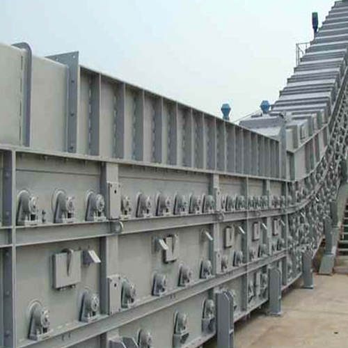
Understanding volume requirements requires looking beyond basic averages. Factory production metrics often mask the chaotic reality of material flow. You must design for the harshest moments of operation, not just the steady baseline.
Tons Per Hour (TPH) establishes your baseline calculation. You match this metric to your factory production rates. Plant managers often provide an average daily yield. You divide this yield by operating hours to find your average TPH. However, relying solely on average TPH often proves highly inadequate for real-world operations.
Average calculations assume a perfectly steady, uninterrupted feed. Industrial environments rarely operate this smoothly. Material flows inconsistently through crushers and hoppers. You must use the average TPH only as a starting point, never as the final design parameter.
Batch dumping creates immediate, massive surge loads. Front-end loaders and hoppers drop extreme material spikes instantly. Imagine a loader dumping 10 tons of slag in just five seconds. Your average TPH might be 100. However, your surge TPH during those five seconds equates to 7,200 TPH.
You must size the system for these peak surge capacities. Designing for steady-state averages causes catastrophic stalling. Overloaded belts spill material, tear edge margins, and halt production entirely. Always apply a surge multiplier. We typically recommend a surge factor of 1.5 to 2.5 times the average TPH, depending on your loading method.
Engineers face a critical decision during system layout. Increasing belt speed boosts capacity without widening the footprint. Unfortunately, faster speeds accelerate abrasive wear exponentially. Abrasion rates typically square with belt speed. Doubling your speed quadruples your wear rate.
Conversely, increasing width maintains capacity at lower speeds. This approach extends equipment lifespan significantly. Slowing down the feed protects expensive belts and idlers from sharp slag edges. It does require a larger physical footprint and higher initial structural costs. However, the long-term operational stability makes wider, slower designs highly preferable.
Theoretical capacity means nothing if the system does not fit your facility. Spatial realities force engineering compromises. You must map your environment carefully to understand how gravity and geometry will affect your throughput.
Steep incline angles significantly reduce effective material-carrying capacity. Gravity causes heavy, round materials to roll backward. This rollback forces you to derate your capacity calculations. Material simply cannot stack as high on an inclined surface compared to a flat run.
You often need cleated designs to maintain throughput on steep angles. Deeper troughing also helps secure the heavy load. Standard smooth belts generally fail to move dry slag efficiently past a 12-degree incline. The angle of repose for your specific slag type dictates these strict limits.
Table 1: Conveyor Incline Capacity Derating Factors
Incline Angle (Degrees) | Material Rollback Risk | Capacity Derating Percentage | Recommended Modification |
|---|---|---|---|
0 - 5° | Very Low | 0% | Standard troughing idlers (20°) |
6 - 12° | Moderate | 10% - 15% | Deep troughing idlers (35° - 45°) |
13 - 18° | High | 25% - 40% | Textured covers or low cleats |
19°+ | Severe | 50%+ (Not recommended for smooth belts) | Bucket elevators or steep-angle pocket belts |
Existing plant structures often limit system dimensions. Narrow corridors restrict available length and width. Low ceilings prevent adequate transfer chute heights. These spatial restrictions force difficult capacity compromises. You might need customized routing solutions or multiple transfer points.
We recommend mapping the exact spatial footprint early in the design phase. Use 3D laser scanning if possible. Ensure you leave adequate clearance for maintenance access on both sides of the framework. A system crammed against a wall becomes impossible to service efficiently.
Loading zones endure massive, repetitive impact forces. High-density materials fall from significant drop heights. The kinetic energy generated by heavy slag dropping just a few feet is immense. Standard idlers will shatter under this punishment.
You must install reinforced impact beds at these transfer points. The severity of these impacts dictates your allowable loading speeds. Heavy impacts require thick, shock-absorbing rubber beds. If your drop height exceeds optimal limits, you must install rock boxes or cascading chutes to slow the material descent before it hits the belt.
Moving beyond basic designs ensures long-term operational survival. Heavy industry requires specialized components built for abuse. You must specify drives, materials, and safety systems that exceed standard minimums.
High starting torques are absolutely essential for heavy loads. Fully loaded belts require massive power to restart after unexpected stoppages. You must select motors and gearboxes explicitly for these intense torque spikes. Undersized drives will stall, overheat, and burn out quickly.
We follow a strict protocol for drive system selection:
Calculate the peak starting torque required under a 100% full load scenario.
Apply safety multipliers based on severe duty classifications (usually 1.5x minimum).
Select heavy-duty gearboxes rated specifically for high shock loads.
Integrate Variable Frequency Drives (VFDs) or fluid couplings for controlled, smooth acceleration.
VFDs prevent snapping belts during high-torque startups. They ramp up the power gradually, protecting mechanical components while ensuring the load begins moving steadily.
Engineers must carefully compare heavy-duty steel pan conveyors against heat-resistant rubber belts. Steel apron designs handle extreme heat and massive loads easily. They excel in environments where temperatures exceed 500°F. However, they require more maintenance regarding chain lubrication.
Rubber belts offer smoother operation and better material containment at lower temperatures. A High Performance Slag Conveyor often utilizes specialized EPDM rubber compounds or wire-mesh reinforced cores. These materials resist tearing while withstanding sustained core temperatures. Your choice depends heavily on localized heat profiling and abrasion testing.
Industry standards mandate strict safety margins for bulk handling. You must design for worst-case overloading scenarios. Regulatory bodies like OSHA and MSHA require robust fail-safes. Emergency stop capabilities must function instantly under maximum capacity loads.
Incorporate zero-speed switches to detect belt slippage immediately. Install misalignment switches to shut down the drive if heavy loads push the belt off-center. Never compromise on these safety compliance metrics. They protect your workforce and prevent catastrophic equipment destruction.
Long-term success depends on how well the equipment survives daily abuse. Maintenance planning is a crucial component of capacity design. A system that breaks down frequently delivers a lower effective capacity than a smaller, more reliable unit.
System utilization rates dictate component degradation speeds. Running continuously at 90% to 100% capacity accelerates wear drastically. Components experience maximum stress and maximum heat simultaneously. Operating at 70% to 80% capacity provides a buffer. This buffer extends component life significantly.
You must balance desired throughput against acceptable degradation speeds. Thickening the belt cover adds protection but increases weight and power requirements. Upgrading to ceramic pulley lagging prevents slippage and extends drive life under high-capacity loads. Plan your wear rates based on realistic operational tempos.
Maintenance accessibility functions as a hidden capacity factor. Frequent shutdowns effectively lower your annual facility throughput. Lengthy repairs destroy production schedules and bottleneck entire downstream processes. You must prioritize systems engineered for rapid component replacement.
Look for slide-out impact beds and externally accessible bearing housings. If replacing a tail pulley requires dismantling surrounding plant infrastructure, your effective capacity plummets during maintenance windows. Accessibility ensures repairs take hours instead of days.
Compare vendor quotes using strict, real-world operational parameters. Do not accept generic proposals. Use this criteria to ensure robust performance:
Demand guaranteed TPH ratings under your specific thermal conditions, not ideal ambient temperatures.
Require documented proof of abrasive resistance standards for all belting or steel pans.
Reject quotes based purely on empty-belt theoretical calculations.
Verify that impact bed load ratings match your maximum calculated drop heights.
Confirm the drive system includes heavy-duty startup torque multipliers.
Sizing this equipment remains a highly complex engineering matrix. It involves variables in weight, volume, temperature, and spatial layout. Capacity is never a single, simple metric. You must view throughput as a dynamic interaction between material behavior and mechanical resilience.
We strongly recommend gathering precise operational data before proceeding. Measure your exact bulk density. Determine your absolute maximum lump size. Map your peak surge TPH accurately. Secure updated, dimensional facility layout drawings to identify spatial constraints early.
Consult with specialized structural engineers before engaging system integrators. Share your gathered data to draft a highly precise Request For Quote (RFQ). By defining these parameters clearly, you ensure your final installation operates reliably, safely, and efficiently for years to come.
A: Engineers calculate base capacity using cross-sectional area, belt speed, and material bulk density. However, this standard formula only provides theoretical throughput. Industrial applications mandate surge multipliers to account for batch loading and inconsistent feed rates.
A: As incline angles increase, material rollback becomes problematic. Gravity pulls heavy materials downward. This rollback reduces the cross-sectional fill rate on the belt. Overall throughput drops by specific percentages based on the angle's severity and material shape.
A: Standard belts degrade rapidly in harsh metallurgical environments. They cannot survive the combination of high bulk density and sharp abrasion. Furthermore, core material temperatures exceeding 400°F (200°C) will quickly melt, crack, or weaken standard rubber compounds.
A: Industrial best practices dictate designing strictly for peak surge loads. Sizing for average production invites catastrophic stalling during batch loading. Peak load design prevents material spillage, prevents motor burnouts, and avoids costly equipment jams.

