
Views: 0 Author: Site Editor Publish Time: 2026-07-31 Origin: Site


Specifying the wrong industrial gate carries severe operational stakes. Premature wear, fugitive emissions, and catastrophic system failures often stem from overlooked procurement details. Matching specific service conditions—such as pressure, temperature, and abrasiveness—with the correct gate architecture is highly complex. Standard off-the-shelf solutions frequently fail when exposed to severe industrial environments. You need a comprehensive, engineering-led evaluation framework. This guide helps facility managers systematically assess specifications, mitigate installation risks, and ensure long-term reliability before ordering isolation gates.
Application Dictates Architecture: Precise identification of material characteristics, flow directionality, and operating pressures is non-negotiable for selecting the correct valve or gate type.
Actuation Impacts Efficiency: Choosing between manual, electric, or a high-performance pneumatic isolation gate depends heavily on cycle frequency, available utilities, and automation requirements.
Seals Determine Lifespan: Material compatibility between the media and the gate’s internal seals is the primary driver of maintenance intervals.
Spatial and System Integration: Physical footprint constraints, structural load capacities, and control system compatibility must be verified prior to ordering to avoid costly field modifications.
Documenting the exact state of the media is your first critical step. You must determine whether the system handles bulk solids, liquids, gases, or abrasive slurries. Variables like bulk density, particle size, abrasiveness, and moisture content directly dictate the required blade material and overall gate design. For instance, handling dry bulk powders requires a different seating mechanism compared to heavy, wet slurries. Knife gates often suit liquid or slurry applications, while slide gates perform better for dry bulk solids. Understanding these dynamics prevents material packing and ensures reliable shut-off. When dealing with highly abrasive materials like fly ash or mining tailings, standard carbon steel blades will erode rapidly. You must specify hardened alloys or specialized coatings to withstand the constant scouring action. Furthermore, moisture content in bulk solids can cause materials to clump and bridge across the gate opening, requiring specific blade bevels or displacement pockets to cut through the hardened material column effectively.
Flow dynamics also dictate the internal geometry of the gate housing. High-velocity gas flows can induce vibration and noise if the gate internals are not properly profiled. Liquid applications with high suspended solid counts require smooth internal transitions to prevent solids from dropping out of suspension and accumulating in the seat area. By thoroughly documenting the physical and chemical properties of the media, you establish the baseline requirements for every subsequent specification decision, ensuring the selected equipment can handle the actual process conditions rather than theoretical design parameters.
Verify exact flange-to-flange dimensions, bore sizes, and the structural load-bearing requirements of the surrounding pipe run. Mismatched dimensions lead to flow bottlenecks and structural stress. Installation orientation also plays a massive role in performance. Mounting a gate horizontally, vertically, or at an incline affects gate travel and stem operation. Horizontal installations might suffer from material buildup in the track, leading to stem binding or incomplete closure. Ensure the surrounding infrastructure can support the weight of heavy-duty Isolation Gates without causing pipe deflection. Heavy cast bodies and large actuators exert significant bending moments on adjacent piping, especially during actuation when dynamic forces are introduced. You must evaluate the need for independent structural supports or pipe hangers directly adjacent to the gate installation point.
Bore sizing requires careful attention to prevent flow restrictions. A gate with a bore smaller than the adjacent piping creates a pressure drop and accelerates wear due to localized velocity increases. Conversely, an oversized bore can create dead zones where material accumulates. Always match the gate's internal diameter to the pipe's schedule and wall thickness. Additionally, verify the flange drilling patterns (e.g., ANSI 150, PN10) to ensure seamless bolting without the need for custom transition spools or field modifications.
Differentiate between unidirectional and bidirectional sealing requirements based on system pressure and backflow potential. Unidirectional gates seal effectively against pressure from one specific direction. Bidirectional designs handle pressure from either side, making them essential for systems experiencing backflow or vacuum conditions. Select the appropriate sealing configuration to prevent upstream or downstream bypass during system isolation. A thorough understanding of flow directionality ensures the gate maintains a bubble-tight seal when closed. In complex piping networks, pressure reversals can occur during pump shutdowns or system upsets. If a unidirectional gate is subjected to reverse pressure, the blade can be pushed away from the seat, resulting in immediate and severe leakage.
Sealing mechanisms vary widely based on these directional requirements. Perimeter seals, O-rings, and specialized packing arrangements must be configured to handle the maximum differential pressure expected across the gate. For critical isolation points where zero leakage is mandatory, double block and bleed configurations or highly engineered resilient seats are required. You must clearly define the acceptable leakage rate and the direction of the primary pressure vector to ensure the manufacturer provides a seating arrangement capable of meeting your isolation standards.
Environmental variables heavily influence gate longevity. You must evaluate the maximum and minimum operating temperatures, line pressure, and ambient facility conditions. Corrosive environments, such as chemical processing plants or frequent washdown areas, require specialized exterior coatings and robust housing materials. Consider the following environmental checklist before specification:
Maximum and minimum media temperatures.
Peak system operating pressure and potential surge pressures.
Ambient temperature fluctuations in the installation area.
Exposure to corrosive chemicals or high-humidity environments.
Presence of combustible dust or explosive gases.
Vibration levels from adjacent rotating equipment.
Seismic zone requirements for structural integrity.
Extreme temperatures dictate not only the seal materials but also the metallurgical choices for the body and blade. High-temperature applications cause thermal expansion, which can lead to gate binding if clearances are not properly engineered. Low-temperature environments can cause elastomers to become brittle and fail. Ambient conditions, such as coastal salt spray or aggressive chemical vapors, necessitate epoxy coatings or full stainless steel construction for external components to prevent rapid surface corrosion and actuator failure.
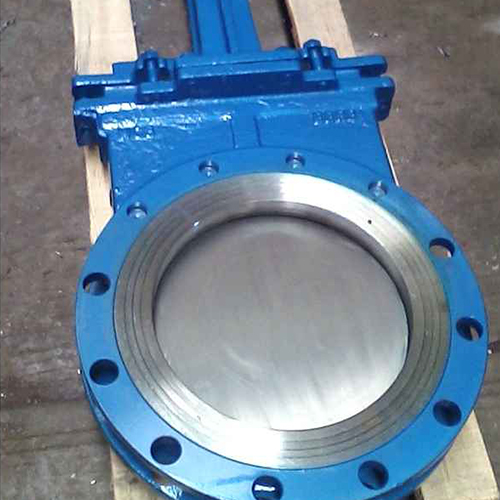
Establish the baseline criteria for manual actuation based on cycle frequency and physical accessibility. Handwheels or chain wheels work well for gates operated infrequently and located in easily accessible areas. However, automation becomes necessary in high-cycle, remote, or safety-critical applications. Relying on manual operation for a gate that cycles dozens of times a day leads to operator fatigue and inconsistent process control. Automated actuators provide precise, repeatable operation essential for modern industrial processes. When evaluating manual options, consider the rim pull force required to operate the handwheel under maximum differential pressure. If the required force exceeds ergonomic guidelines, gear operators must be specified to provide mechanical advantage.
Automation introduces a layer of complexity but offers significant operational benefits. Automated systems can be integrated into plant-wide control architectures, allowing for remote operation, sequence timing, and automated fail-safe responses. The decision to automate should be driven by the process requirements, safety protocols, and the physical location of the equipment. Gates located in confined spaces, elevated platforms, or hazardous zones should always be automated to remove personnel from potentially dangerous environments during routine operations.
Pneumatic systems offer rapid actuation, high cycle counts, and reliable fail-safe configurations. A High-Performance Pneumatic Isolation Gate utilizes compressed air to drive the blade, providing swift response times critical for emergency isolation. When integrating pneumatic systems, verify available plant air pressure and air quality. Ensure the cylinder sizing matches the required closing force to cut through moving media. Additionally, specify air accumulator requirements if the system demands fail-safe stroke actions during a power loss. Pneumatic cylinders must be sized with a sufficient safety factor to overcome static friction, dynamic flow forces, and potential material buildup in the seat.
Air quality is a frequently overlooked factor in pneumatic system reliability. Plant air must be clean, dry, and properly lubricated (if required by the cylinder seals) to prevent internal corrosion and premature seal failure. Specify filter-regulator-lubricator (FRL) units for each automated gate to condition the air supply locally. For applications requiring precise positioning or modulation, pneumatic positioners can be integrated, although isolation gates are typically used for strict on/off service. The speed of actuation can be controlled using exhaust flow restrictors to prevent water hammer in liquid systems or structural shock in heavy bulk solid applications.
Electric actuators provide precise positioning and seamless integration with modern Programmable Logic Controllers (PLCs). They excel in environments where compressed air is unavailable. However, they have limitations in explosive environments unless equipped with specialized, heavy-duty enclosures. Hydraulic actuation suits applications requiring extreme thrust forces to shear through dense materials. While hydraulic systems deliver immense power, they require rigorous maintenance to prevent fluid leaks and manage hydraulic power units. Electric actuators offer advanced diagnostic capabilities, providing real-time feedback on motor torque, valve position, and operating temperatures, which is invaluable for predictive maintenance programs.
Hydraulic systems are typically reserved for the most demanding applications, such as large-diameter gates handling heavy slurries or mining ores. The incompressible nature of hydraulic fluid provides rigid control and massive shearing force. However, the infrastructure required—including hydraulic power units (HPUs), high-pressure hosing, and fluid reservoirs—adds significant complexity and maintenance overhead. Environmental concerns regarding potential hydraulic fluid leaks must also be addressed through secondary containment and the use of environmentally acceptable lubricants (EALs) where applicable.
High-force automated actuators introduce significant safety risks, including pinch points and sudden gate movement. Protecting maintenance personnel during line interventions is paramount. Specify mechanical locking pins to physically block gate travel during servicing. Safety shrouds and guards must cover moving components to prevent accidental contact. Dedicated lockout/tagout (LOTO) hardware ensures the system remains completely de-energized and physically secured before any maintenance work begins. The design of the locking mechanism must be robust enough to withstand the full force of the actuator if it is accidentally energized while pinned.
Guarding should be designed for easy removal during maintenance but must be securely fastened during operation. Clear visual indicators of gate position (open/closed) are essential for operator safety and process verification. Proximity switches or mechanical limit switches should be wired into the safety interlock system to prevent upstream equipment from operating if the isolation gate is not in the correct position. Comprehensive safety documentation and training must accompany the installation of any high-force automated equipment.
Differentiate between internal seat leakage and external fugitive emissions. Internal leakage allows media to pass downstream when the gate is closed, while external leakage releases media into the surrounding environment. Industry standards, such as ANSI/FCI or MSS classes, define acceptable leakage rates. Specify the appropriate leakage class based on safety regulations and environmental impact. Strict emission controls require highly engineered packing glands and resilient seating materials to maintain zero-leakage performance. Fugitive emissions are heavily regulated in chemical and petrochemical applications, requiring live-loaded packing systems that maintain constant pressure on the seal as it wears.
Internal leakage tolerances depend on the criticality of the isolation. For maintenance isolation where personnel will be working downstream, bubble-tight shut-off (Class VI) is often mandated. For less critical process diversion, a lower leakage class may be acceptable and can reduce the required seating force and actuator size. Testing protocols, such as hydrostatic or pneumatic seat testing, should be specified in the procurement documents to ensure the equipment meets the required leakage class before it leaves the manufacturer's facility.
Selecting the right construction materials prevents premature degradation. Carbon steel suits standard applications, while 304 or 316 stainless steel provides necessary corrosion resistance. Abrasion-resistant alloys are mandatory for handling highly abrasive media like mining slurries. Elastomers and polymers require careful selection based on chemical compatibility and thermal limits. PTFE, EPDM, and Viton offer different resistance profiles. Match the seal material precisely to the media to prevent swelling, cracking, or thermal degradation. The wetted parts of the gate must be evaluated independently from the external housing, as they are exposed to the full aggressive nature of the process media.
Common Seal Materials and Applications | |||
Seal Material | Temperature Range | Primary Applications | Limitations |
|---|---|---|---|
EPDM | -40°F to 250°F | Water, steam, mild chemicals | Poor resistance to petroleum oils |
Viton (FKM) | -15°F to 400°F | Oils, fuels, harsh chemicals | Not suitable for steam or hot water |
PTFE (Teflon) | -100°F to 450°F | Highly corrosive chemicals, food grade | Rigid material, requires higher seating force |
Polyurethane | -30°F to 180°F | Highly abrasive slurries, bulk solids | Low thermal tolerance, poor chemical resistance |
Graphite | Up to 1000°F+ | High-temperature gases, steam | Brittle, requires careful handling during installation |
When selecting blade materials, consider surface treatments and coatings that can enhance performance. Hard chrome plating, nitriding, or tungsten carbide coatings can significantly extend the life of a stainless steel blade in abrasive service. The body material must also be evaluated for galvanic corrosion potential if it differs from the adjacent piping materials. Proper isolation gaskets and bolting materials must be specified to prevent galvanic cells from forming at the flange connections.
Verify compliance with relevant safety and operational standards before finalizing specifications. OSHA regulations dictate the necessity of safety guards and LOTO provisions. Facilities handling combustible dust must adhere to ATEX or NFPA standards to prevent ignition sources. Food and beverage processing requires FDA or USDA-compliant materials and sanitary designs. Ensuring regulatory compliance mitigates legal risks and guarantees the equipment meets established safety benchmarks. Documentation, including material test reports (MTRs) and certificates of compliance, should be requested during the procurement phase to verify the pedigree of the materials used.
Pressure vessel codes, such as ASME Section VIII, may apply to the gate housing depending on the operating pressure and volume. Compliance with these codes requires specific design calculations, welding procedures, and non-destructive testing (NDT) during manufacturing. Failure to specify the correct regulatory standards can result in equipment that is illegal to operate or poses a severe safety hazard to plant personnel.
Analyze the operational demands placed on the equipment. Define duty cycle expectations by calculating the frequency of operations per hour or day. A high duty cycle accelerates wear on gate components, seals, and actuators. Specifying a highly engineered, application-specific gate extends service life significantly compared to standard commodity options. Downtime and frequent maintenance interventions disrupt production schedules. Evaluating the expected service life ensures the selected equipment withstands the rigorous demands of your specific process. A gate that cycles once a month requires a vastly different design approach than one that cycles every five minutes.
High-cycle applications demand robust bearing systems, heavy-duty stems, and wear-compensating seal designs. The actuator must also be rated for continuous duty to prevent overheating or premature seal failure. By accurately defining the duty cycle, you allow the manufacturer to select components that will provide reliable operation over the intended lifespan of the equipment, reducing the frequency of unplanned outages and production losses.
Evaluate the design for in-line serviceability. Determine if maintenance teams can replace packing or adjust seats without removing the entire gate from the pipeline. In-line serviceability drastically reduces maintenance downtime. Supplier reliability plays a crucial role in long-term operation. Review warranty terms and confirm the guaranteed availability of proprietary replacement parts. Partnering with a manufacturer that provides robust aftermarket support ensures you have access to critical spares when needed. Gates designed with split bodies or removable seat rings allow for rapid field repairs, minimizing the impact on production schedules.
Consider the standardization of components across your facility. Selecting a single manufacturer or a standardized gate design reduces the required inventory of spare parts and simplifies maintenance training. Request a recommended spare parts list during the procurement phase and ensure that critical wear items, such as packing, seals, and limit switches, are readily available from domestic distribution centers to prevent extended lead times during emergency repairs.
Identify common spatial risks before equipment arrives on site. Insufficient overhead clearance for the actuator prevents proper installation. A lack of access space hinders maintenance personnel during routine servicing. Structural interference with existing piping or supports causes significant installation delays. Require 3D CAD models from the manufacturer to run interference checks within your facility layout. Verifying spatial constraints prior to ordering prevents costly field modifications and ensures a smooth installation process. Pay special attention to the withdrawal space required to remove the blade or actuator for servicing.
In tight installations, consider alternative actuator configurations, such as parallel-mounted cylinders or bevel gear operators, to reduce the overall height or width of the assembly. Ensure that electrical and pneumatic connections are accessible and do not interfere with adjacent equipment. Proper planning during the design phase eliminates the need for torch-cutting structural steel or rerouting piping during the installation outage.
Address the risks of mismatched control signals between the gate’s instrumentation and the facility’s central control system. Positioners and limit switches must communicate seamlessly using compatible protocols, such as 4-20mA, HART, or Profibus. Incompatible signals lead to integration failures and loss of process control. Involve control engineers in the final specification review to verify technological compatibility. Proper integration ensures accurate position feedback and reliable automated operation. Specify the required electrical classifications (e.g., NEMA 4X, Class I Div 1) for all instrumentation to ensure it survives the ambient environment.
Wiring terminations and conduit entries must match the facility's standard practices. Provide the manufacturer with detailed electrical specifications, including voltage requirements for solenoid valves and switch contact ratings. Factory acceptance testing (FAT) should include a full functional test of all instrumentation to verify correct wiring and signal output before the equipment is shipped to the site.
Compile a comprehensive application data sheet detailing media characteristics, operating pressures, and environmental conditions.
Request detailed general arrangement (GA) drawings and 3D CAD models to verify installation clearances.
Initiate technical consultations with shortlisted vendors to review custom engineering support and verifiable case studies.
Involve control and safety engineers to validate actuator compatibility and LOTO provisions.
A: Isolation gates are designed primarily for on/off service to completely stop or allow flow. They provide a tight seal to isolate sections of a pipeline. Control valves are engineered to modulate and regulate flow rates, pressure, or temperature continuously within a system.
A: Measure the nominal pipe size and match the flange drilling patterns exactly. Account for specific flow characteristics and media volume to ensure the bore size does not create bottlenecks or restrict system throughput.
A: Choose a pneumatic gate for scenarios requiring rapid actuation, high cycle frequencies, and fail-safe open/close functionality upon power loss. They are also ideal in environments where compressed air is readily available and electrical sparking presents a significant hazard.
A: Manufacturers require critical data points including media type, maximum and minimum temperatures, operating pressure, flow rate, actuation preference, pipeline dimensions, and any specific regulatory compliance requirements.
A: Mounting a gate horizontally or in an inclined position can cause material buildup in the track, uneven seal wear, or stem deflection. These orientations often require specialized guide supports, displacement pockets, or self-cleaning designs to function reliably.
A: Standard safety requirements include implementing strict lockout/tagout (LOTO) protocols, using physical isolation pins to block gate travel, and installing protective guard covers to prevent accidental contact with moving parts.
A: Specify gates engineered with displacement pockets, self-cleaning clevis designs, or integrated air-purge systems. These features are specifically designed to clear bulk solid materials from the seating area during closure.

